Radio Boulevard
Western Historic Radio Museum
 

Rebuilding the ART-13 Transmitters

Part 1
 

General Information about the ART-13

Selecting an ART-13 Candidate for Restoration

Deciding How to Power the ART-13
(Dynamotor Operation or "Homebrew" AC Power Supply, Dynamotor Servicing)
 

information found in parts 2, 3 and 4,....

Restoration Hints and Suggestions

"Basket Case" Restoration Project & Three Other Restoration Projects

Building a Suitable AC Power Supply (includes Three Schematics)

How to Setup and Operate the ART-13 Today

Operating the ART-13 on LF 630M (472kc)
 

by: Henry Rogers WA7YBS/WHRM

photo above: Radioman's position on a Douglas DC-4 using an ART-13 and two BC-348 receivers - Radio News Jan 1950

When it comes to vintage WWII military radio transmitters, it's pretty hard to beat the ART-13. It's a potent 100+ watt transmitter that doesn't "weigh a ton" and has the potential to provide first-class audio in the AM mode. On top of that, parts needed for a restoration are usually easy to find and most of the circuitry is not too difficult to work on. Also, I've included construction data, including schematics, on three different ART-13 AC power supplies that I've built. Certainly every restorer/operator has their own techniques and the prospective ART-13 owner should read everything available on the Internet about these popular military transmitters to help them decide on a project that best suits their abilities and their goals.   H. Rogers - May 10, 2011


General Information about the ART-13
 

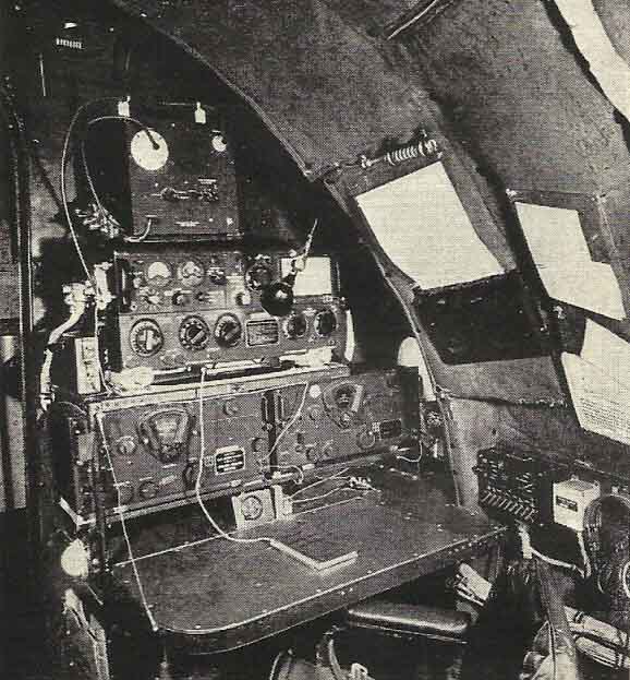
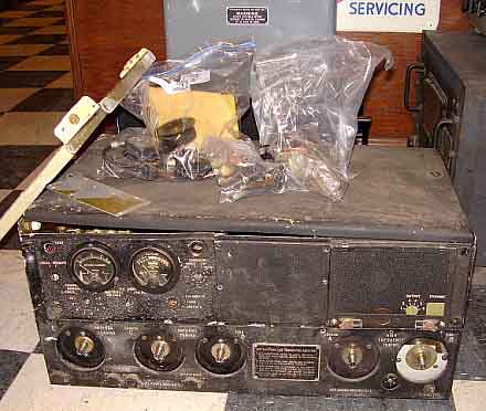
The Collins T-47/ART-13 is a 100 watt carrier output, AM-CW-MCW transmitter that was generally used in USN and USAAF/USAF aircraft but could also be found onboard USN ships as the TCZ installation. There were even some vehicular uses for the T-47/ART-13. The T-47/ART-13 was developed from the earlier Collins ATC Aircraft Transmitter that appeared around 1940. In 1940, the Collins ATC was tested in competition with the Bendix ATD and possibly the RCA ATB. The Collins ATC won easily as the competition lacked many of the ATC's modern features. By 1942, Collins had updated the ATC  and designated it as the T-47/ART-13. The USAAF also wanted to use the T-47/ART-13 and a very slightly different transmitter was produced for their use, designated as the T-47A/ART-13 (later designation was AN/ART-13A.) Probably the first USAAF use of the T-47A/ART-13 was in the B-29 bombers where they were paired with the BC-348 receiver and designated ARC-8. The USN had many installations in Grumman torpedo bombers and the Curtis Helldiver dive bomber along with 
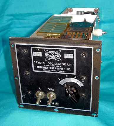
shipboard uses. There was also a T-412/ART-13B that added a 20 channel HF and 4 channel LF oscillator by retrofitting earlier versions of the ART-13. At the end of WWII, the transmitters were designated as AN/ART-13, AN/ART-13A and AN/ART-13B. There are many other different designations assigned to ART-13 transmitters that are essentially identical to the three basic ART-13 variations. Various end users account for most designation variations found.
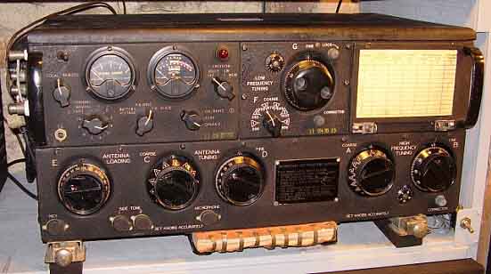
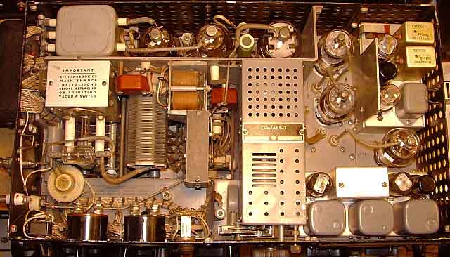
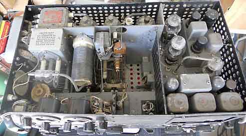
Basic Transmitter Circuit - The ART-13 uses a permeability tuned oscillator designated as a VFO (although later these types of VFOs were referred to as a PTO - permeability tuned oscillator - by Collins.) The VFO-PTO operates from 1000kc to 1510kc that is tuned using two ranges that are switched alternately as control A is changed. The first range is from 1000kc to 1200kc and the second range is from 1200kc up to 1510kc. The VFO tube is a 837. The VFO-PTO output is routed to the first Multiplier that increases the frequency for the various tuning ranges of the transmitter. Below 6.0mc only the first Multiplier is used as either a doubler, tripler or quadrupler depending on the frequency desired. Above 6.0mc the second Mulitplier is also used (only as a tripler) to achieve these higher frequencies. Two 1625 tubes are used as the Multipliers. The Multiplier(s) feed the 813 PA and its output is matched to the antenna using a tuner that can select either an L or a Pi network depending on the frequency and load matching necessary. Controls C, D and E tune the antenna matching network. AM is achieved using a 12SJ7 speech amp and a 6V6 amplifier that drive the pair of 811 modulator tubes. CW is via a keying relay operating the PTT line. The transmitter can be tuned from 2.0mc up to 18mc.

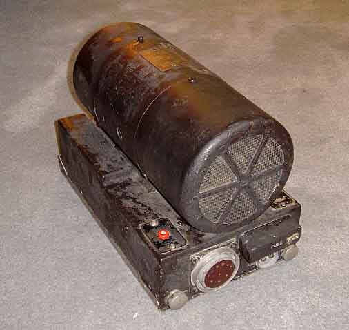
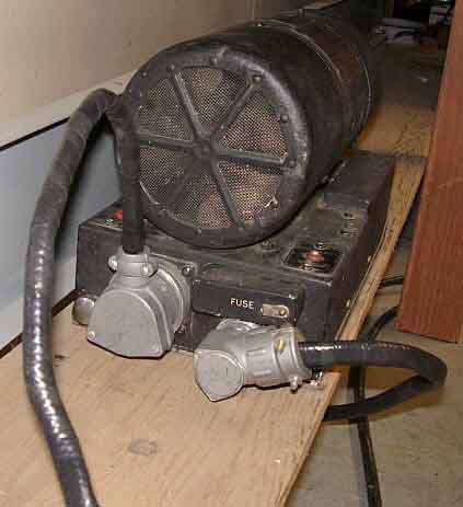
Power Requirements and Accessories - 
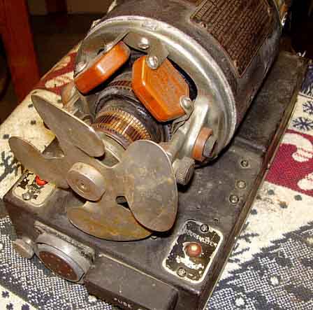
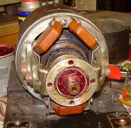
The T-47/ART-13 power requirements were supplied by a dynamotor that ran on the aircraft +28vdc battery/charger system. The aircraft battery buss supplied the +28vdc@10Amps necessary for the transmitter's tube filaments and relay operation while the 
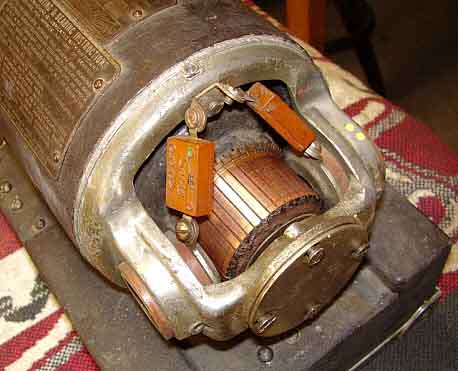
dynamotor provided a dual output of  +400vdc and +750vdc. The dynamotor would have the two B+ levels connected in series for the HV Plate ( +1150vdc) below 20,000 to 25,000 feet altitude but a barometric pressure switch (located inside the dynamotor housing) would separate the outputs at higher altitudes and only 
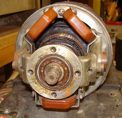
allow +750vdc maximum to prevent arc-over. There were four types of dynamotors used. The earliest was the DY-11 that was used with the ATC. The DY-12 was used with the ART-13. The DY-17 was used with the ART-13A and WWII versions of the ART-13B. Post-WWII, there was a DY-17A produced. All four dynamotors are interchangeable to power any ART-13. 
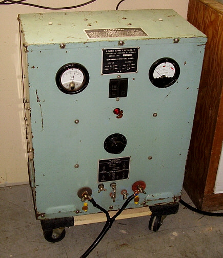
The shipboard TCZ featured two types of power supplies, a 115vac operated, floor-mounted pedestal-type power supply that provided the required +28vdc, +400vdc and +1150vdc directly to the transmitter. The 115vac unit utilized a motor-generator that provided +14vdc and +28vdc @10A (the +14vdc was required for relay operation inside the AC or DC operated TCZ power supply and the +28vdc operated the tube filaments and relays in the transmitter.) The +400vdc and +1150vdc were provided by standard AC transformer power supplies. The 115vdc operated TCZ power supply used two dynamotors that ran on 115vdc input and provided +14vdc and  +28vdc output on one dynamotor and +400vdc and +1150vdc on the second dynamotor. The USMC had a vehicular set-up that installed an ART-13 transmitter with a BC-348 receiver that operated from the back of a Jeep and ran on the +28vdc battery system with HV provided by a DY-12 dynamotor. The antenna was a whip.

Power and Remote Receptacles - There are three large multi-pin connectors on the left side of the cabinet for applying voltage input, remote control operation and LF control line. The connectors are marked as follows (from front to rear:)

PLUG U-8/U - Remote channel select, standby, audio, PTT line (T-R)
PLUG U-7/U - Voltage inputs from dynamotor, PTT line (T-R)
PLUG U-11/U - Low Frequency Loading Coil (Tuner) PTT line (T-R)

The U-11-U connector is only used with the CU-32 Antenna Loading Coil (LF Tuner.) The U-8/U connector is used with the pilot's remote that allowed remote control of the ART-13 from the pilot's seat. Also, receiver remote standby is accessed from the U-8/U connector. U-7/U is the connector for applying all voltages to the transmitter and providing the ability to turn the ART-13 "on or off."


photo above: US Navy T-47/ART-13 built by Collins Radio Co. ca. 1943
 

Autotune - The T-47/ART-13 featured an advanced Autotune system that would automatically "tune" up to 11 preset channels (10 channels plus going to the LF output) selectable by a front panel switch. The Autotune system would mechanically set the transmitter frequency and output network components to presets that then would result in the transmitter matching a properly selected antenna. The ART-13 didn't automatically load and tune itself to an unknown antenna load as more modern Collins' transmitters would (e.g., the T-195) but assumed the operator would connect the proper type of antenna for the channel selected on the ART-13. The Autotune cycle took about 25 seconds to complete.

Setting the presets required selecting a specific desired channel (Channel 2, for example,) then loosening the Lock Bar on each of the individual controls, setting those control to the desired or necessary position (that is, tune the transmitter to the tuned frequency with the specific antenna load connected) and then re-tightening each of the Lock Bars. Then, the next time that channel was selected, the Autotune would reset all of the controls to the preset positions for that channel.

Switch position MANUAL would allow manual adjustment of the tuning  without disturbing the Autotune presets. MANUAL had to be selected with the transmitter powered up so the Autotune would properly "mechanically" select the MANUAL position (in other words, with power off you couldn't just place the switch in MANUAL and be in MANUAL.)

Some transmitters had orange triangles on the backing plates of each of the Autotune Controls. When the Locking Bar was tight, these orange triangles were covered and not visible. If the control was "unlocked" (Locking Bar not tightened) then the orange triangles would show and the operator would know immediately by just looking at the transmitter not to operate the Autotune until the "unlocked" control had its Locking Bar tightened. Autotune operation of an "unlocked" control will then require repeating the set-up for that particular channel.

Vacuum Tube Information - The T-47/ART-13 uses an 837 as the variable frequency oscillator, two 1625 tubes are used as multipliers, an 813 as the power amplifier and two 811 tubes as the P-P modulators. There are also two small modules. One provides the audio amplifier and sidetone amplifier using two 6V6 tubes and a 12SJ7 tube and the other module, the MCW/Frequency Calibration Indicator, uses two 12SL7 tubes and a 12SA7 tube. FCI allows the operator to calibrate the frequency of the transmitter by providing a 50kc calibration signal derived from a 200kc crystal oscillator. The earlier ATC transmitter used a slightly different FCI module that used two tubes and had a rather large plug-in crystal (see interior photo of ATC below.)

Low Frequency Coverage and More Accessories - The standard ART-13 transmitter frequency range is from 2.0mc to 18.0mc, however many Navy ATC and T-47/ART-13 transmitters and later USAAF T-47A/ART-13A transmitters were equipped with a plug-in Low Frequency Oscillator (LFO) module that allowed the transmitter to operate from 200kc to 600kc or 200kc to 1500kc (at somewhat reduced power, CW only for electrically short antennae.) Early LFOs had a frequency range of 200kc to 1500kc in six ranges designated as O-16/ART-13, while the later LFOs cover 200kc to 600kc in three ranges and is designated as O-17/ART-13A. The LFO modules used a single 1625 tube. If 630 meter operation is desired then be aware that the O-16 LFO "splits" the 630 meter band with a range change at 475kc. There's enough "overlap" to cover the entire 630 meter band at the edge of either range selected. When the LFO is in operation the ART-13 Multiplier section is bypassed and the LFO output directly drives the PA.

There are some indications that the Navy set-ups used the 200kc to 1500kc LFO while the USAAF used the 200kc to 600kc LFO. Most versions of the T-47/ART-13 will have a blank plate installed where the LFO module was installed designated as NX-128/ART-13. These LFO "dummy panels" had a resistive load included that substituted for the LFO's 1625 filament load. It's possible the most of the LFOs were removed later in the ART-13's life as the transmitters were usually on HF after WWII. According to the USAF Extension Course 3012 book on "Radio Mechanics from 1950," the Navy was still using LF after WWII but the USAAF wasn't.

When switched to LF, the ART-13 PA output is capacitively coupled (via the plate blocking capacitor) to "LOADING COIL" terminal J-117. Selecting the LF position also disconnects the ART-13 internal HF antenna matching network. The aircraft installations (when operating LF) would require the CU-25 or CU-32 antenna tuners (called Antenna Loading Coils.) These units provided the antenna matching networks for low frequency operation of 200kc up to 600kc. There was also the CU-26 that provided antenna matching for 500kc up to 1500kc. The CU-32 allows the use of either trailing wire or fixed antennae while the CU-25 and CU-26 are for trailing wire only. Generally, the Navy used the CU-25 and CU-26 while the USAAF used the CU-32.

Also most installations on aircraft included a small Remote Control Panel designated as C-87/ART-13 or a smaller remote designated as C-470/ART-13. The remotes allowed the pilot to operate the transmitter from the cockpit. The larger C-87/ART-13 has a hand button for keying the ART-13 and allows a microphone connection at the remote. A typical aircraft ART-13 installation could select from a couple of different remotes, three different types of LF antenna tuners, a triple fixed capacitor (CU-24 auxiliary capacitor for antenna loading below 7mc - each capacitor was 25pf in value for a maximum available C of 75pf) along with various antenna and capacitor-selecting knife switches. There were at least a couple of different shock mounts that were available depending on the version of ART-13 and where it was located. Shock mounts provided vibration isolation and elevated the transmitter to allow convection cooling. Most installations seen in vintage photographs usually have two BC-348 receivers. Later (usually post-WWII) aircraft installations may have the ARR-15 receiver.


photo left: Inside a Collins' version USN T-47/ART-13 showing the LFO module installation. Also, the later three-tube version of the MCW/FCI module is installed. Note that the chassis is painted gray on Collins' version

The Chassis Layout - To the left is a photo showing the chassis of an early Collins-built T-47/ART-13. This transmitter has the Navy version LFO installed. Also, this is a fairly early version of the transmitter so there are some differences when compared to the T-47A/ART-13 versions. Of note is the lack of an interlock switch which on the early versions allows you to easily operate the transmitter with the lid off. The module to the lower right is the Audio Amplifier unit and directly behind it is the 837 VFO tube. Behind the VFO tube is the FCI/MCW module and to the left of it are the two 1625 multiplier tubes. The module in the center of the transmitter is the LFO. In the section at the rear of the transmitter, to the left side is the modulation transformer from which its plate leads connect to the two 811 modulator tubes. To the right of the 811s is the 813 PA tube. The left-center section of the transmitter contains the matching network and the LF relay (next to the LFO module.) On the far left is the vacuum TR switch and behind it is the keying relay. The round ceramic unit in front of the vacuum TR switch is the inductive pickup for the Antenna Current meter.

T-47A/ART-13 or AN/ART-13A - The somewhat later USAAF T-47A/ART-13 aka: AN/ART-13A version added some minor improvements to the transmitter with a vernier scale on the VFO Fine Tuning, a top lid interlock switch, a different bottom plate with built-in guides for the shock mount and a white ceramic insulator bell on the antenna connection being among the most apparent changes. This model of the transmitter is often found built by various contractors with Stewart-Warner (CWS) and Zenith (CZR) being the most often encountered (Zenith was an early contractor having built some of the ATC versions.) The contractor identification is most often found on the metal tag mounted on the right side of the transmitter as initials incorporated into the serial number.

Conversions/ MWOs - Almost all earlier ATC and early ART-13 will have several MWO updates added to the transmitter. It's common to find that the FCI/MCW module is the later version, also that a lid interlock has been installed. Sometimes the later style base mount is installed. The MWO IDs are usually stenciled on the right side of the transmitter with the letter "M" followed by a number from 1 to 6 identifying the MWO. Sometimes the original ATC data tag will be replaced with a T47/ART-13 tag.

T-412/ART-13B or AN/ART-13B - There was also a T-412/ART-13B that added a 4 channel LF/MF and 20 channel HF crystal oscillator module, the CDA-T in place of the LFO module. The CDA-T was built by Communications Company, Inc.(aka COMCO,) who generally supplied the module with a full installation kit that included extensive instructions and directions for the conversion of either the ATC, the T-47/ART-13 or the ART-13A. When the CDA-T was installed and the transmitter fully converted to the "B" version then, with the selection of each of the transmitter channels 1 to 10, two different crystals could be selected giving the user two frequencies per channel or a total of 20 HF channels in all. Also with the CDA-T installation a "frequency extension" modification was added that changed the lower end of the frequency coverage down to 1670kc. The LF position allowed the selection of four crystal controlled frequencies on the CDA-T module. The remote used with the "B" version will have a toggle switch to allow selecting either crystal frequency per channel selected.

All "B" versions of the ART-13 are conversions of earlier ART-13 or ATC transmitters. Be aware that you can't just install the COMCO module and have your ART-13 become a "B version. In fact, the CDA-T can't even plug-in to an unmodified ART-13. The installation of the "B" version CDA-T module required extensive modification of the transmitter circuitry along with the addition of a second Jones Plug for the module and an additional wafer for the REMOTE-LOCAL switch along with several additional components (supplied in the kit with the module.) Most ART-13B conversions that were performed by the military during WWII will have riveted tags installed to identify the frequency extension toggle switch and another tag riveted above the original transmitter data plate that identifies the conversion to T-412/ART-13B. Post-WWII conversions generally don't have these riveted tags installed. Since there was no modification to the Autotune of the ART-13 transmitter, each of the A/B crystal channels had to be set very close in frequency to each other, otherwise the transmitter wouldn't be tuned for one or the other of the lettered crystal channels.
 

photo left: The Crystal Oscillator Unit for the ART-13B. Built by Communications Company, Inc. (COMCO.)

Post-WWII Use - The T-47/ART-13 had a very long life. Introduced around 1942, actively used during and after WWII and well into the sixties. The Grumman HU-16 air-sea rescue amphibians were equipped with ART-13/BC-348s until the late 1960s. The USSR also produced a copy of the ART-13 that they used up to the late 1980s (the R-807.) Surprisingly, the ART-13 was available on the surplus market quickly after WWII ended. By 1946, one could purchase an ART-13 with all of the accessories for between $75 and $125. Most were fully checked out and guaranteed to work. Many hams bought the ART-13 as a station transmitter, some operating the transmitter on its dynamotor while most built AC power supplies instead. The availability changed fairly quickly and by 1950 only a few surplus dealers offered the ART-13. Civilian airline companies also began using the ART-13 in various commercial airliners. Many were converted to the B version for multiple crystal-control channels (there was also a C version which was similar in function.) Some ART-13s were supplied to civilian aircraft in new condition with priority sales which probably accounted for the shortage in the surplus market after 1950.

Because of its long useful life, most T-47/ART-13 transmitters found today will have many scratches and a few dents and several paint scrapes. Nearly all transmitters encountered today will have been through various military depots for repairs or upgrades many times over its years of use. Most transmitters will have non-matching (updated) modules with some parts having MFP applied and others that are bare. Usually, the right side of the transmitter case will have various MWO numbers stenciled to indicate what upgrades were installed (usually M1 through M6 were always installed on earlier transmitters.) Mis-matched meters are common to depot repairs. Almost all military transmitters will have the Microphone switch safety wired in the CARBON position unless it has been recently worked on by hams. 

A book containing brief instructions and the calibration settings for specific frequencies is usually stored in the metal pocket underneath the transmitter.  Earlier versions of the transmitter will have a somewhat thinner (and always missing) book not "chained" to the pocket. This earlier book is specifically for the two tube version of the MCW/FCI module used in the ATC and early T-47 transmitters. Later versions have a thicker book that is specific for the three tube version of the MCW/FCI module used in late T-47 and all ART-13A versions. The later book has a plastic tubing covered chain that was supposed to keep the book "tied" to the transmitter. This later book is also usually missing on most transmitters (although the same information is in the standard manuals.) Luckily, many tens of thousands of T-47/ART-13 were built and spare parts are very easy to find which allows for the fairly easy restoration and maintenance of these durable and potent transmitters.

 photo above: The Collins ATC chassis showing some of the differences between this very early version and the later ART-13. Notice the earlier, two tube version of the MCW/FCI module (the large cylinder upper right is the crystal) and the absence of the large LF relay K-105 (smaller version is in ATC.) Also note the Collins tag on the modulation transformer. This transmitter appears to have been hit in the front as both grab handles are broken.
 

Selecting an ART-13 Candidate for Restoration


Preliminary Considerations

Assessing your potential restoration candidate prior to purchase is important for a successful completion of the project. Choosing the right ART-13 is certainly going to determine how long it takes you to complete the project and get it "on the air." There are a couple of tests that should be made if you have access to the transmitter before purchasing. Also, some things to look for when buying on line.

Technical Difficulty of Restoring an ART-13 - The ART-13 is a robustly-built but light-weight, compact transmitter. Since it is fairly small most of the components are installed into tight quarters and accessing most of the transmitter circuitry will require some disassembly. Fortunately, most of the transmitter design and construction allows easy disassembly to access and work on various parts of the circuitry. If you have serious problems in the Autotune section, this is difficult to disassemble and some of the parts are somewhat delicate. Same goes for the VFO-Multiplier sections which are difficult to access and the Multiplier uses very delicate stacked trimmer capacitors. Though the Audio and MCW/FCI modules are easy to remove, the components are densely mounted under the chassis. Most ART-13s will have MFP applied and this will compound the difficulty of any soldering work that might be required. Certainly an AC power supply (if opt'd for) will be the most time consuming to design and build. >>> >>>  You should have the following skills when taking on an ART-13 project. You should have some experience working on tube-type transmitters and working around high voltages. You should be experienced in full disassembly and reassembly of electronic equipment. If you decide on an AC power supply, you should possess "homebrewing" skills, that is, sheet metal working, component layout, proper wiring lead dress, etc. You should have good technician skills, possess a good soldering technique and use real SnPb solder with first class soldering equipment. You will need good quality test equipment and know how to use it. You will need a set of spline wrenches (also called Bristol wrenches) for all set screw applications. An oscilloscope is essential during testing and set up of the transmitter. You should possess good troubleshooting skills. Most hams that have worked on several tube-type transmitters and have built some radio equipment will have the necessary skills to complete the restoration of an ART-13.
Selecting a Candidate for Restoration - There are a lot of ART-13 transmitters for sale at swap meets, on eBay, from Fair Radio Sales or from various online sources. ART-13s are not hard to find. But, what is hard to find is a good condition, all original and complete ART-13. Most of the transmitters that are for sale look like the one in the photo to the right. Not a good candidate unless you are experienced and looking for a real challenge*. This candidate's condition is obvious but many times the ART-13 you are looking at can have serious problems that aren't obvious at all. A thorough inspection followed by actually testing a couple of the components can help "weed out" a transmitter that is going to need a lot of repair and restoration work.

A good candidate should be fully assembled and have all of its modules installed. A few missing tubes are okay since they are easy to find and not terribly expensive. Be aware though, missing tubes should be taken as an indicator that the transmitter was considered a "parts source" at one time and may actually have some operational problems - not always - but definitely investigate further if all of the tubes are missing. Meters should be in good condition and they are easy to test while in the transmitter. The meters are not difficult to locate but the same caveat as with missing tubes should be considered. Generally, a complete and good condition transmitter means it has always been stored correctly, has not been abused and probably has a pretty good chance that nothing serious will be found wrong in the circuit or with the components. Be skeptical though! Even though the transmitter might look great, it could have a serious, difficult to solve problem that kept the transmitter from ever being used, thus it's excellent appearance. Definitely, any transmitter that is missing parts should be considered  a "restoration project" that is going to require time searching for parts and will need more time to get the fully operational.

*See section below "T-47A/ART-13 'Basket Case' Restoration" to see how this transmitter turned out.

photo right: T-47A/ART-13 "parts set." Note, even the multimeter glass is broken. Although restorable, this one would be a definite challenge.

Inspecting the ART-13 Before Purchase

Thorough Inspection of the Transmitter - If you have access to the transmitter prior to purchase you can look it over in detail. The two "easy to remove" modules should be present. The three-tube MCW/FCI module is easy to find if it's missing but the Audio module is more expensive and a little more difficult to locate. Check the interlock switch on the T-47A/ART-13 versions since if the transmitter is placed upside down with the lid off (for quick and careless repair work) more than likely the switch will be broken. Check the wiring for anything cut or missing. >>> >>>  Check for broken parts. The Antenna vacuum switch is sometimes broken since it is a glass unit. Undo the locking bars and see if the controls rotate easily. Don't "force" any controls that seem stuck - you'll only break something. The controls should freely rotate. Check the condition of the push connectors on the left side of the transmitter and make sure they aren't corroded and stuck. Also, check the condition of the U/7 connector and make sure the pins aren't bent or corroded. That's about all you can check visually. If the seller is agreeable, check the Modulation Transformer and the Meters as described in the following sections.
Testing the Modulation Transformer - This is probably the most important part of the transmitter that is sometimes missing and other times non-functional. Finding a good condition replacement (if you need one) is difficult and somewhat expensive. You will want to know "up front" if the ART-13 you're contemplating buying has a non-operational modulation transformer as this will seriously affect its selling price. You'll need to have a DMM (Digital Multimeter) to check the modulation transformer. You will be measuring the DC resistance (DCR) of the windings. This test is not a 100% indication that the modulation transformer is perfect but it's a pretty good test. Also, if the DCR of a tested winding reads open, you then know 100% for sure that the mod transformer is bad. Take care to make good contact to the terminals with your test probes, especially if the mod transformer is coated with MFP. Note that each of the seven terminals are numbered. The three terminals on the left side (assuming you're in front of the transmitter) are from left to right looking at this side 6, 7 and 2. On the right side the four terminals are left to right 1 and 3 on top and 4 and 5 on the bottom.

Be aware that the 813 screen windings have a different DC resistance on early units. The change occurred about the middle of the ART-13A contracts. It looks like the wire used for the the screen winding was increased in diameter for better durability which would then have the same turns ratio but a lower DCR. It's also possible that many of the earlier Mod transformers were noisy. My T-47/ART-13 has the earlier Mod transformer and it is very noisy when at full modulation. My AN/ART-13A sn: 417ACG however, has the later Mod transformer and it is quiet regardless of the modulation level. I have also tested ART-13A sn: 2054 that has the early style mod xmfr and have found that it also is somewhat "noisy." The implication is that the lower screen DCR (heavier gauge windings) helped to reduce the mod xmfr "talk-back." Subsequent testing has shown that this "talk-back" virtually doesn't exist when the plate voltage is running at spec, or around +1100vdc. My earlier "talk-back" experiences were when a USN ART-13 transmitter was operated on +1400vdc plate voltage and experiencing "talk-back" then later the same transmitter operated on +1100vdc plate voltage with virtually no "talk-back." This condition only seems to affect the earlier mod transformers with the later mod transformer operating a high plate voltages without "talk-back."     >>>

>>> Here is the DCR between the various terminals with the Modulation Transformer installed in the transmitter (with power off, of course.)

Terminal 2 to Terminal 3 = 136 ohms DCR

Terminal 2 to Terminal 1 = 123 ohms DCR

This test measures the DCR of the P-P 811 modulator plate winding. Terminal 2 is the CT of the winding.
 

Terminal 7 to Terminal 6 on early mod xmfrs = 150 ohms DCR

Terminal 7 to Terminal 6 on later mod xmfrs = 38 ohms DCR

This test measures the DCR of the 813 screen winding
    

Terminal 4 to Terminal 5 = 112 ohms DCR

This test measures the DCR of the 813 plate winding
 

If the transformer measures close to these DCRs, it is likely in good condition and useable.

NOTE: If you want to check the windings to chassis for case shorts be sure to place the CAL/TUNE/OPERATE switch in OPERATE. If you have that switch in the TUNE position, you'll have a 25K short to chassis on the 813 screen windings.

Testing the Antenna Current Meter - This is an AC current meter that is driven with an adjustable core, single-turn transformer. The meter is .250mA FS and should to be checked with an AC source, such as a Function Generator. The Function Generator will have a very low output Z - probably 50 ohms. The polarity to the meter doesn't matter but you will have to disconnect it from T-102, the Antenna Current Transformer. Set the function generator frequency to anything higher than 100kc - it's not critical. It takes a pretty high level sine wave signal to move the Antenna Current meter needle but 15 volts Pk-Pk should read 2.0 Amps on a working meter. If a Function Generator is not available, a Digital Multimeter (DMM) will indicate around 3.0 ohms DCR across the terminals in both directions (due to the internal dual thermocouple) but the meter needle should not move with DC applied (from the DMM measuring DCR.) Again, you'll have to disconnect the meter for testing by either method. Generally, these meters were pretty reliable and are seldom non-functional. Testing the Multimeter - This meter is a 1mA FS DC meter. Measure the DCR across the terminals and you should read about 40 ohms DCR.  NOTE: Be sure to only use a Digital Multimeter (DMM) for this measurement. Older style VOM meters can apply enough voltage in some of the ohm scaling to do possible damage to the ART-13's multimeter. With a DMM, you will see some deflection of the meter needle. Be sure to observe the correct polarity. You are only checking the meter's continuity with this test, not its accuracy. To check the accuracy you would need a small DC voltage source that is adjustable and a 300 to 1000 ohm load resistor. Use the DMM set on DC mA with the FS at no higher than 10mA. Use the load resistor to limit the DC voltage source and connect the meter, the load resistor and the DMM in series with the DC voltage source. Adjust the DC voltage for a FS meter reading and then look at the DMM. It will read how much current is necessary to drive the meter FS. It should be very close to 1.0mA Toilet Seat Covers - These are the protective covers that are usually on the KEY, both SIDE TONE and the MICROPHONE jacks. The T.S., or Throttle Switch (remote PTT,) jack doesn't have a protective cover. These are mentioned here because some ART-13 variations will be found without the Toilet Seats installed. This is correct for certain sub-model variations. All ATC versions don't have toilet seats. NT-52286 is another variation that did not have the protective covers and there may be others. Check the panel carefully for originality if the Toilet Seats are missing. Original installations use rivets to mount the covers so any removal operation would be obvious. 
Buying an ART-13 Online - If the only source available to you is eBay or QTH.com or some of the other online venues, your inspection is going to be cursory, at best. Photos only show so much and detail is often lacking. Most of the time the seller doesn't show what is important and has several irrelevant photos. You should ask questions or ask for more photos. Generally, if the transmitter appears to be in great condition, then it probably is complete and was stored carefully. You won't know the condition of the components unless the seller has taken the time to test them and will guarantee their condition. Buying online, especially on eBay, will result in paying the highest price, plus paying for shipping (where damage may also occur.) Since you will be paying "top dollar," you should be assured that the transmitter is in good condition and will be packed carefully for shipping. Modified ART-13 Transmitters - The ART-13 was the subject of many modifications generated by the CQ magazine crowd. CQ published "The Surplus Conversion Handbook" which contains two or three articles on ART-13 "modification for ham use." Although we cringe today at such "hacking," it was commonly done in the fifties and sixties. Consequently, finding an ART-13 in modified condition is fairly common. Some of the mods were intended to increase the transmitter's frequency coverage. There were mods to extend the lower end to cover 160M, although many ART-13s will tune about 25kc into the top of the 160M band without any modification. There were other mods to extend the upper end to 10M. The 10M mod pretty much did extensive damage that is difficult to restore to original. Also it's very common to find some of the Antenna/Condenser/Loading Coil/Ground push connectors replaced with SO-239 UHF coax receptacles. Again, damage to the connector panel is usually irreparable.

Try to stay away from modified ART-13 transmitters. There are a several minor upgrades or modifications out there that have some benefit and enhance the performance but generally the ART-13 can be operated in its original configuration without any problems.

Manuals - Since so many of the manuals are available on-line, it's probably a good idea to download them and become familiar with the transmitter before you actually purchase one. That way you'll know what to look for and how to describe certain parts of the transmitter that are somewhat unique.

T.O. 12R2-ART13-2 is the Maintenance Handbook for the ART-13A and is a very good source of information. Available on BAMA (Boatanchor Manual Archive)

NAVWEPS 16-30ART13-5 is the Maintenance Handbook for the ART-13. Available on BAMA

Several other manuals were published over the years. Some are available on-line but the majority of these lesser known manuals have to be purchased from other sources.


Deciding How to Power the ART-13

By now you should be considering how you're going to power up your ART-13 when you finish the restoration. I'm not trying to talk the potential ART-13 operator out of using an original Dynamotor set-up but there are several "pit-falls" that will surface when attempting this method of operation. The initial purchase of the equipment necessary to operate the dynamotor will be fairly expensive but one should remember, once a high-current power supply is purchased, you can run almost any dynamotor set-up with it. However, due to the fact that many ART-13 owners aren't necessarily vintage military radio enthusiasts, building an AC-operated power supply is the least expensive and most common approach taken to power up an ART-13. Usually the most time-consuming part of the entire ART-13 restoration project is deciding how to power the transmitter and then obtaining the necessary components to accomplish the task. The following information comparison may help you come to a decision.

Using the Original Dynamotor Set-up


photo above: The DY-12/ART-13 dynamotor

Dynamotor Details - Any versions of the ART-13 transmitter can be powered by any of the four versions of dynamotor that were produced. The original ATC was supplied with the DY-11 dynamotor. The T-47/ART-13 was supplied with the DY-12. All later ART-13 transmitters used the DY-17 or DY-17A dynamotor. To power any of the dynamotors requires using a shielded cable that uses two 8 gauge wires that are connected to the dynamotor with a large two-pin Cannon plug and are then routed to the +28vdc power source. There is a small third pin for the shield in the original connector. The dynamotor generally requires about 32 amps (max. at voice peaks at full modulation VOICE mod) at +28vdc at full output. Typical I is 8 amps at idle and 26 amps "key down" no modulation.

The dynamotor is connected to the ART-13 via a shielded cable that utilizes two different types of Cannon plugs. The dynamotor-side uses a 10 pin male plug and the transmitter-side uses a 10 pin female plug. All three of the original Cannon plugs are available for many sources (although they are not cheap!) Generally, the power cable has to be built. The ART-13 power cable uses two 14 gauge wires (pins 5 & 6,) five 18 gauge wires and two 16 gauge wires. These are the minimum gauge size that should be used. Larger wire sizes have less voltage drop. I use 12 gauge for pins 5 & 6 and 16 gauge for the other seven wires and I use the center conductor and insulation from a length of RG-58 coax for the +HV wire on pin 10. The power cable has to be shielded. I use the braid removed from RG-8U coax. Push the coax shield together to expand its inner diameter and then sleeve it over the 10 wire cable. Once in place, pull the shield tight and wrap the entire cable with two layers of electrician's tape. Install the connectors and be sure to connect the shield using a "drain wire" to the connector shell on both ends. The ART-13 manual will have a schematic and breakdown of the the power cable. Build the +28vdc cable in the same manner. Use minimum of 8 gauge wires (6 gauge is better) and connect the shield to the small pin of the connector. Be sure that the shield is connected to the negative of your high current DC power supply.

The differences in the four versions of the dynamotors are locations of the reset switches which are on top of the base on the DY-11 and DY-12. The reset switches are on the front panel of the DY-17 models. The end bells differ on all three models with the DY-11 having a circular screened vents, the DY-12 has six spokes in its screened vents and the DY-17 has three spokes in its screened vents. Although there are some minor circuit changes between the models these changes don't affect how the dynamotors power any of the ART-13 transmitters.  >>>

>>>  The photo above shows a DY-12 dynamotor which was originally supplied with the T-47/ART-13 version of the transmitter. This particular dynamotor was built by Wincharger Corp. (aka Winco) and, although in kind of "rough" condition, it does function correctly. The input and output box connectors are identical for all versions of the ART-13 dynamotors. The photo right shows the DY-12 in service. This shows how the dynamotor connectors look.

The DY-11 and DY-12 are difficult to find and usually are in original condition which means they may require some rebuilding to function well. The DY-17 is the more common version but it's still difficult to locate. Since most casual ART-13 "parts collector-dealers" think the DY-17 is the only proper dynamotor, it is usually the most expensive one to purchase, if it can be found. Same holds true for the later DY-17A. In all cases, any newly purchased dynamotor should be serviced before using.

Another word of caution on dynamotors in general,...dynamotors may be found that have problems that can't easily be repaired. A shorted armature might require rewinding and, if you can find anyone to do it, the costs will be staggering. A recent quote to rewind a DY-17A armature was $3300 from a rebuilder in Los Angeles! If you want to go the dynamotor route, try to arrange a test of the unit prior to purchase to see if it will operate correctly when powering an ART-13. Even with a shorted output-side armature, the dynamotor will rotate since the motor-side winding is okay making the tester think the dynamotor works. However, under load (trying to operate an ART-13) the defective dynamotor will "bog down" and not rotate at speed due to the excessive load of the shorted armature and the ART-13. You must test the dynamotor actually powering up an ART-13 before you know it's usable.

The specifications for the input and outputs are as follows:

Input:   +27vdc at 32amps - with the aircraft aloft, the charging buss was nominally running at +28vdc (sometimes slightly higher) and this is where the dynamotors work best. The +27vdc spec allowed for some voltage drop in the power cable from the dynamotor to the buss.  

Outputs:   +400vdc at .750amps   and   +750vdc at .350amps  IMPORTANT NOTE: Since the +750vdc is in series with the +400vdc to provide the +HV, the +400vdc has a current requirement that is doubled, that is current for +LV and current for +HV. This is the current that the dynamotor can supply, not the current that the ART-13 requires.

Dynamotor Operation - If you decide to go original and use one of the dynamotor-battery combinations, here's some other things to think about.

Running the Dynamotor only on Batteries (not recommended) -  Using two 12vdc deep-cycle marine batteries connected in series to provide +24vdc for dynamotor/xmtr power is not recommended. The batteries will have to be kept charged in some manner. Charging lead-acid batteries in the house or ham shack can be dangerous and certainly is smelly. Additionally, the batteries alone will only provide about +26vdc after charging and the voltage will drop rapidly as the transmitter/dynamotor is in operation. In the airplane, the transmitter/dynamotor ran on a battery-charger system that provided an almost constant +28vdc while the airplane was aloft. This is where the ART-13 runs best. Typical power output using the dynamotor on just batteries will be around 60W to 70W. With a charging system (+28vdc) power output should be over 100W. This is due to the speed that the dynamotor turns. The +28vdc turns the dynamotor at its rated RPM where it delivers the rated voltages. At lower battery voltages, the dynamotor speed drops and so does the voltage along with the transmitter power output.

Running the Dynamotor with a High Current AC PS (best solution)To eliminate the batteries and run the dynamotor on a high-current +28vdc power supply is problematic due to the horrendous starting current required to operate the dynamotor. Although when turning at full speed (and powering the transmitter) the dynamotor load and the transmitter load requires around 35 amps, the initial starting current required by the motor section of the dynamotor is close to 100 amps. Although this starting current is very high it only lasts for a few milliseconds, that is, until the armature begins to move at which time the current demand drops rapidly as the motor armature comes up to speed. Even though the high current demand is for a very short duration, many modern, high current DC power supplies with current fold-back circuitry or other types of protection circuits will "see" the dynamotor as a "short circuit" and prevent the power supply from operating. The exceptions are some of the earlier military heavy-duty AC power supplies. These are early style "linear" supplies that can handle the surge current demand since it only lasts for a few milliseconds. The GRC-106 power supply is rated at +28vdc at 50Amps and, if one can be located separated from the transceiver, it will operate the DY-17 (et al) dynamotors. Also, the heavy-duty "battery charger" unit, the PP-1104, can be used to supply +28vdc at well over 50A. These types of heavy-duty power supplies can provide more than enough current to start the ART-13 dynamotors. Also, there are portable airport-type power supplies used for starting airplane engines. These are available up to 200 amps at +28vdc. However, "expensive" is an understatement. More details on the PP-1104 below.

Running with a Combination of Batteries and Hi-I AC PS (might be necessary in some cases)Another solution is to run the lead-acid batteries with an adjustable 0 to +50vdc power supply capable of providing at least 20 to 40 amps. That way, you can adjust the power supply to have the battery system at +28vdc and simulate a charging system. The batteries will provide the 90 to 100 amps necessary for the initial starting current of the dynamotor. In essence, this combination simulates how the ART-13 operated while on the aircraft aloft. This system may work with high current linear power supplies that have current fold-back circuits, but experimentation would be necessary since I haven't tried that combination. However, the hassle of running both batteries and a high current power supply seems to complicate a problem that can be easily solved by using either the PP-1104 or GRC-106 PS.

Using the PP-1104 to power the ART-13 with a Dynamotor - Details - The PP-1104 was originally supplied to the military as part of a battery charging system. To say that the power supply is robust is an understatement. It is capable of supplying well over 50 Amps at 28vdc and has the ability to adjust the output voltage to compensate for the load. There are two versions of the PP-1104, the early version that uses a large selenium rectifier and the later version that uses silicon diodes. Both have similar performance specifications. Early versions are designated as PP-1104-A/B and later versions are designated as PP-1104-C. Many different contractors have built these power supplies over many years so there are variations galore as to minor construction details and paint colors, etc., but the specifications and performance are all the same. The physical size of the PP-1104 is about 24" tall by about 20" wide by about 12" deep. The weight is over 100 lbs for the early versions and just at 100 lbs for the later versions. The original AC line requirements were either 115vac or 230vac with the current draw at around 10 amps when operating on 230vac and around 24 amps when operating on 115vac with some variation depending on the output load. NOTE: Typical AC line voltages encountered nowadays are 120vac or 240vac which doesn't present any problems for powering the PP-1104C units. The power supply can also be set up for 12vdc at over 100amps capability. The circuit uses two 12vdc solid-state linear power supplies that can be connected in parallel or in series via front panel links. Meters provide constant monitoring of output voltage and current. A front panel switch allows for setting the output voltage in roughly 10 steps. Output voltage should not be adjusted with the unit turned on however. Set the output voltage switch with power off and then check with power on. The circuit on the later PP-1104 supplies uses a magnetic amplifier to increase the current capabilities. Also, a very small internal power supply feeds into the main supply to provide voltage regulation. 

The PP-1104 was built for years by many different contractors. The Gladding-Keystone version that I've used for many years is from a 1967 contract. The latest contract version I've seen was from 1989. With a little searching, a PP-1104 should be pretty easy to find. The selling prices vary but expect to pay around $200 to $300+ for a decent one. NOTE for May 2022: I just purchased two 1989 contract PP-1104C units, both built by Astra Products from Olman, Flordia. These units both are in excellent condition and appear to have had very little use over the years. Both of these PP-1104C are set up to run on 240vac.

Curing RFI in the PP-1104 - Some PP-1104-C versions are rather noisy in the RF spectrum and the magnetic amplifier will produce some RFI. These units can be set-up with shielded AC lines coming in and shielded cables for the output. Be sure that the case of the power supply is also connected directly to the station ground system with a 10 ga. ground wire. Additionally, it's a good idea to bypass the AC line in with .01uf capacitors to chassis and to also bypass both the positive and negative output terminals with a .22uf tubular and a .01uf ceramic disk capacitors connected to chassis. Be sure to check the 10-32 screws that mount the top cover, the bottom and the back cover to see if good grounding contact is being achieved. Usually the paint is very heavily applied and quite hard which insulates the covers from making good contact to the main frame. It's usually necessary to use a small sanding disk to remove the paint where each screw head makes contact and remount the screws using toothed lock washers. This will provide an "RF tight" enclosure which helps considerably in reducing RF noise. Thanks to Jerry W6JRY for the PP-1104 RFI suggestions.

Operation - Using the PP-1104 to operate dynamotors eliminates most of the headaches since the power supply is capable of providing the starting current without hesitation. Also, since the PP-1104-C can be adjusted to over 40vdc output voltage, adjusting to 28vdc under load is easy and allows the ART-13-dynamotor combo to run efficiently and with maximum RF output power (100 to 110 watts typically.) You might find that the unloaded voltage (when you're not transmitting) might be a little high running up to maybe 30vdc but it is possible to adjust the PP-1104 to find the best compromise of loaded versus unloaded conditions. You shouldn't adjust the PP-1104 when it is operating, so some experimenting will be required. Also, if you use the largest gauge wire that will fit in the connector sockets in your ART-13 to Dynamotor cable and the PP-1104 to dynamotor cable, the less voltage drop you'll experience and thus the less voltage change between load and no load conditions. Typical excursions with large gauge wires in your cables is between 1vdc and 2vdc maximum. Usually, you can set the PP-1104 for +28.5vdc no load and under load the voltage will be +27.5vdc, which is ideal. Remember that the ART-13 tube filaments are running on the PP-1104 in both transmit and receive, so try to keep the supply voltage as close to +28vdc nominal as possible. Also, the PP-1104 runs more efficiently on 240vac than on 120vac. Most noticeable will be the instantaneous output voltage drop when switching on a heavy load will be greatly reduced when the unit runs on 240vac. Still, operation on 120vac will be trouble-free except in very rare cases.


photo right
: A 1967 PP-1104-C built by Gladding-Keystone Corp. A little bit scratched up but still working fine. Note that the voltage meter (left) is a replacement meter. Also, note the small moving dolly used for easy relocation of this heavy power supply

Servicing the ART-13 Dynamotors

This write-up relates the servicing procedure (with photos) of the DY-12 version of the ART-13 dynamotor. The servicing procedure is the same for each of the ART-13 dynamotor versions. There will be slight differences in end bells and the base but, internally, the DY-11, DY-12, DY-17 are very similar. The DY-17A has some significant component changes internally but the output voltages and rating are the same.

Most of the dynamotors we encounter haven't been serviced in a very long time. Maybe the original grease is still in the bearings. You never know until you take the dynamotor apart and check. Generally, if you remove the end bells you can access most of the areas of interest. You'll want to check the following:

1. Condition of the brushes

2. Condition of the commutator segments

3. Type and amount of grease in the bearings

Remove the brushes to check length and the surface that contacts the commutator. You will have to remove all of the brushes even if the brushes are in good condition because of the cleaning solvents used to remove the old bearing grease could contaminate the brush surface. Keep the brushes clean by removing them before the cleaning process. The brushes are marked "+" and "-" for proper location. The dynamotor frame also is marked "+" and "-" and for "MV" and "HV" to aid in proper brush location. Also, the brushes are usually inserted with the "+" or "-" facing up.

The brushes should fit the contour of the commutator. The brushes should also be long enough to not run hot. Usually about 1/4" minimum above the bottom edge of the housing is okay. If the brushes are too short then they should be replaced with new brushes. If the brushes need replacing then you'll probably have to go to a motor rebuilding shop or other source of brushes to find a set that are the correct dimensions. Normally, the original brushes are okay because the military serviced the dynamotors when they were in use and when the dynamotors went to surplus they were never used again. Consequently, the brushes are usually in decent condition. If you do purchase new brushes they will have to be contoured to fit the commutator closely. This can normally be accomplished with fine sandpaper that is placed around a wooden form that's the same diameter as the commutator. The goal is to have the brush surface perfectly match the shape of the commutator. This will reduce brush wear and eliminate "sparking."


photo above: The +HV and +LV side of the dynamotor before cleaning


photo above: The +28vdc commutator after cleaning.

The commutator segments should be bright and smooth and not exhibit any grooving or wear. Light cleaning can be done with very fine sandpaper held against the segments while the armature is rotated by hand. The photo above shows how the commutators looked on this DY-12 before cleaning. Most of the time, the light cleaning is all that's needed. Again, the dynamotors were maintained in the military and afterwards seldom, if ever, used. Be sure to clean the grooves between each segment after the light cleaning. Sometimes conductive residue can get into the grooves and cause problems. Clean with denatured alcohol and an acid brush. The fan should be removed for better access to the +HV and +LV commutators. The set screws have to be almost withdrawn from the fan hub since the shaft has recessed holes for the set screws. Also, on the +HV and +LV side, removing the top two bypass capacitors will give better access to that commutator. 

The ball bearings will normally need some attention. Again, while in the military, they were greased when the dynamotor was serviced, but since then, they have probably never even been inspected. You'll normally find that there is grease present but it has hardened to the point of becoming wax or even harder. Usually though, the old, hard grease will soften when saturated with WD-40. Use WD-40 as a solvent to spray the bearings. Use an acid brush or small stiff paint brush to work the WD-40 into the bearings. This should clean out most, if not all, of the old grease. The ball bearings should spin freely at this point. Photo below left shows the original grease before repacking.

Now, work new grease into the ball bearings. Don't use that old, stringy, yellow grease that the military used back in the 1940s (even if you could find it.) Use modern high temperature wheel bearing grease. This type of grease is easy to find at any place that sells auto parts and is usually transparent red. Use your thumb and fingers to "press" the new grease into the ball bearings until they are almost full. Replace the gaskets and covers. Be sure to clean and install any shims that adjust the thrust movement of the armature. Photo below right shows the bearing with new grease before the cover was reinstalled.

Since you've repacked the bearings, clean the commutators with alcohol again to make sure there's no grease on the segments. Replace the brushes and brush retaining caps. If you've marked the orientation and location, everything should go together easily and correctly. Install the end-bells. You might have to clean their mating surfaces for easier installation. Connect the dynamotor to a voltage source and to the ART-13 for a load. Upon switching on power and actuating the PTT on the ART-13, the dynamotor should rapidly come up to speed and power up the ART-13. The bearings should be running quietly,...well, as quiet as a large dynamotor runs anyway. If everything is correct, the ART-13 should produce a little over 100 watts output when running on a good condition dynamotor (that's powered by a PP-1104-C or similar power source.) When PPT is released the dynamotor should "coast" to a stop in a few seconds. This shows that the brushes are riding smoothly and the bearings have ample lubrication.

For more details on cable building and operating the ART-13 with a dynamotor go to "Operating the T-47/ART-13 with the DY-12 Dynamotor" further down this page

CONTINUE TO PART 2


ART-13 Part 3                        ART-13 Part 4                     Return to Home Index


Radio Boulevard
Western Historic Radio Museum


Vintage Radio Communication Equipment Rebuilding & Restoration Articles,

 Vintage Radio History and WHRM Radio Photo Galleries

1909 - 1969

- 60 years of Radio Technology -


This website created and maintained by: Henry Rogers - Radio Boulevard, Western Historic Radio Museum © 1997/2023