Radio Boulevard
Western Historic Radio Museum


RCA's Amazing AR-88 Series of Receivers
Receivers from WWII ~ AR-88D, AR-88F, AR-88LF, CR-91, DR-89, RDM
 
  Receivers from post-WWII ~ CR-88, CR-88A, CR-91A, SC-88, OA-58A/FRC, CR-88B


Part 1 - History and Design  - The Various Models - Detailed Information

Part 2 - Triple Diversity Models - Russian Ham Users - AR-88 Serial Number Analysis & Log

               Operational and Modification Caveats - Restoration Suggestions

Part 3 - Sweep IF Alignment  - RF Tracking Alignment

Part 4 - Operating AR-88s in Diversity - Performance Comparisons

              AR-88 Performance Today - Easy and Reversible Muting Mod  
 

by:  Henry Rogers - WA7YBS Radio Boulevard/WHRM

AR-88 - During WWII Enemy Signal Intercept was its Primary Duty
 

  (as depicted in the 1956 Norwegian film "Konakt!" - photo from ON4ROB)


PART 1


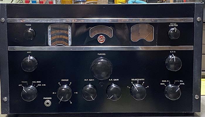
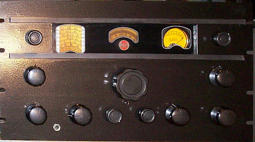
RCA AR-88D - 1944 version

History of the AR-88 Series


RCA's greatest general purpose communications receiver creation was the AR-88, a receiver that achieved its renown by providing top performance and high reliability in service as a surveillance and intercept receiver during WWII and later as a "workhorse" for the RCA and Radiomarine Corporation of America coastal stations, usually in triple diversity receivers that provided world-wide ship-to-shore message handling. RCA's AR-88 planning may have chronologically followed their AR-77 ham receiver but the AR-88 owes much of its design concept as a replacement for RCA's marine-durable, very expensive commercial-military receiver, the AR-60. The AR-60 had been introduced in 1935 and was still being built as late as 1940 (CGR-32-1 USCG contract Nov. 1939.) RCA did produce a small quantity of AR-80 receivers that were a more robust, portable version of the AR-77 for the military but the circuit wasn't as sophisticated as the AR-88. RCA had to come up with a modern, highly reliable military/commercial product that would meet the needs of WWII and the AR-88 was the result. Design stages probably date from as early as late-1939 and the demands of  WWII in Europe pushed RCA into having the AR-88 ready by early 1941. The finalized AR-88 was a 14 tube superheterodyne that covered .54 to 32MC in six tuning ranges, featuring incredible sensitivity (even up to 10 meters), excellent stability and high fidelity audio along with mechanical and electronic reliability that couldn't be found in most other receivers of the day. The electronic design was the work of Lester T. Fowler while George Blaker handled the mechanical design. The actual production during WWII was handled by RCA's Export Sales under Charles Roberts in Camden, New Jersey. Additional receivers were produced at RCA facilities in Bloomington, Indiana and Montreal, Quebec, Canada. Grisby-Grunow Co. is sometimes mentioned as an AR-88 contractor during WWII but this company went bankrupt in 1934.

The AR-88 Outside the USA - Most of the early AR-88 production was sent to Great Britain or Russia (and to a lesser extent China and France) during WWII through Lend-Lease and this accounts for the scarcity of the early versions of the receiver in the USA. The Lend-Lease Act of October 1941, allowed the USA to supply materiel to our Allies in exchange for permission to build and operate bases in the allied countries or territories.

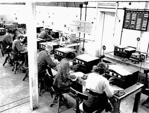
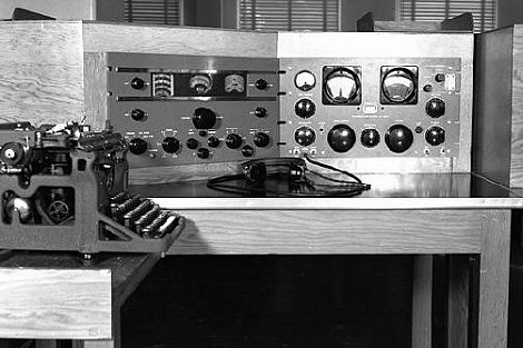
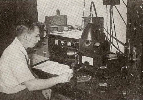
The AR-88 was used extensively in Great Britain during WWII for varied purposes. The photo to the left shows Special Operations Executive's (SOE) Wireless Receiving Station STS 53b at Poundon, Oxfordshire, England in early 1945. This station provided message reception and communications with SOE agents.

photo from: Richard Smith, whose mother is operating at Station 36 (foremost op.)

Many of the Allies required coverage of the LF and MF parts of the spectrum and the AR-88LF was created for that service, providing coverage from 70kc to 550kc continuous and 1.5mc to 30mc continuous. Building of the AR-88LF receivers was handled by the RCA plant in Montreal, Quebec, Canada. RCA-Camden, NJ, USA supplied the CR-91 receiver possibly to supplement demand for AR-88LF-type receivers.


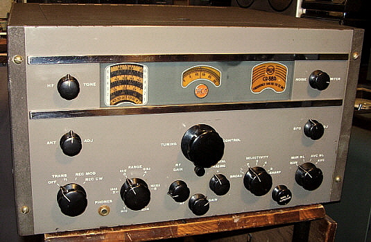
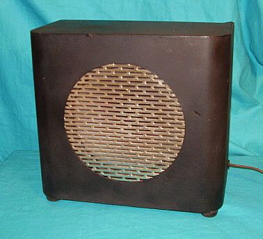
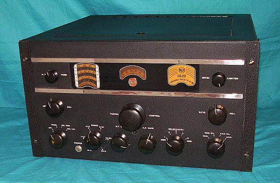
The CR-91 - Camden-built version of the AR-88LF from 1944

By the end of WWII, it certainly seemed like tens of thousands of AR-88 receivers had been shipped overseas to our allies. However, careful examination of serial numbers indicate a production level that was far less than the customary published estimates. While it may have seemed like "AR-88s were everywhere" the actual production numbers did not exceed 25,000 units (total WWII production of AR-88D, AR-88F, AR-88LF and CR-91 receivers, that's still a lot of receivers.)

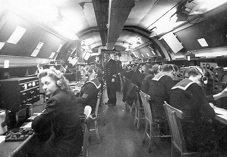
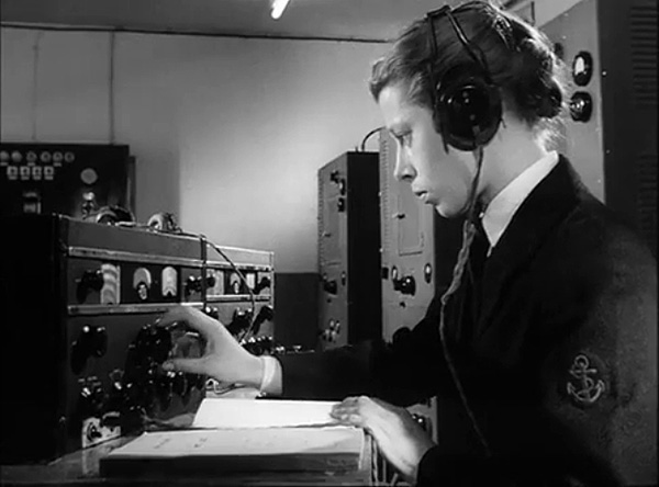
The AR-88 was used for several purposes by Great Britain during WWII. This is a photo of the Portsdown Tunnel communications center that handled wartime communications. Note that the WREN (Womens Royal Navy Service) to the left is using an AR-88 as the communications receiver.


photo from: www.portsdown-tunnels.org.uk  

Many of the British AR-88s were destroyed after WWII ended. This was due to the provisions in the Lend-Lease Act which stated that materiel had to be either returned or destroyed. In just one incident, a load of AR-88 receivers was "dumped" into an abandoned well by USA forces after the war ended. Some sources even indicate that RCA had made it clear they did not want to see the receivers back in the USA for any reason. The AR-88 survivors, along with other surviving materiel, generally were placed in groupings that were "sold back" to Great Britain at discount, which was usually at "ten cents on the dollar" or less (and was probably based on the "scrap value" rather than the original cost.) 
 

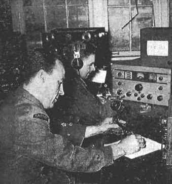
Still, lots of the AR-88s survived and they were considered a common and easily available receiver in Great Britain for several decades after WWII. The easy availability of AR-88s made them a popular amateur receiver in the 1950s and 1960s. Shown to the right is the typical British ham, G5FA, with his AR-88D station receiver. It appears the receiver is an early version with solid yellow tuning dial. Photo is from the G5FA QSL card.

AR-88s survive in Russia because a large quantity were sent over as part of Lend-Lease in the later part of WWII (after the USSR became an Ally.) The receivers were used for both surveillance and communications during the war. After the war ended, it is assumed that none were returned and it's unlikely that any were destroyed. The USSR continued to utilize the AR-88 after WWII as it had during the war, that is for military and surveillance purposes. By the late-1950s, the AR-88 was showing its age and the receivers became available to ham club stations. By the late-1960s and early-1970s, it was very common to QSO Russians on 20M CW who were using an AR-88 for the station receiver.  More on UA-UK use of the AR-88 in the section "AR-88 and Russian Hams" in Part 2.    >>>

AR-88s survived in Canada because some of the receivers built in Montreal during WWII remained in Canada for various needs there. The AR-88LF versions, which were only built in Montreal, found their way to airports, civilian and military, ship-to-shore coastal stations around Canada and for general communications. Although Canada did export most of the AR-88LFs to Great Britain, some did remain behind for wartime use. After WWII, commercial users, such as the airports and coastal stations, did continue using their AR-88LFs for sometime. Eventually, most of the receivers have made it to the Canadian government surplus sales and many were available though other Canadian surplus outlets.


photo right: VE1HO Stadacona, NS in Canada using the CR-88 version in their club ham station. photo from: www.jproc.ca
The AR-88 Inside the USA - After WWII, RCA and Radiomarine Corporation of America (a division of RCA that handled all of RCA's maritime radio business and operations) continued to use the AR-88 and its variants in their own installations for various purposes. Most were in large coastal stations that provided worldwide ship-to-shore message handling via RCA Radiograms.
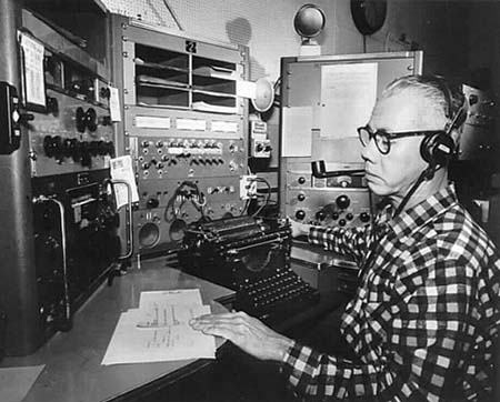
Although single receiver operation was common, RCA/RMCA also utilized the AR-88 at installations in a triple diversity receiver designated the DR-89. In late-1945, RCA replaced the AR-88 with the CR-88 which placed the Crystal Phasing control on the front panel and reduced the size of the RF Gain and AF Gain control knobs so all three controls would fit just below the tuning dial. The CR-88A replaced the AR-88F in the diversity receivers.


photo left: Radiomarine Corp. Coastal Station KPH operator, Fred Baxter, flanked by two RCA CR-88 receivers and a Collins 51J-4 receiver. Photo from KPH History website:  www.radiomarine.org

Even the US Military used some of the later AR-88 variations in their installations that required a high performance, highly reliable receiver. During the latter part of WWII the Navy had used a Triple diversity receiver that was essentially the RCA DR-89 but was given the Navy designation of RDM. This diversity receiver was mainly used for data transmission in the form of CW, High-Speed CW and RTTY. Voice could be used but the RDM was primarily for reliable data reception. After WWII, the Navy continued to use the RDMs up to the 1970s. By 1949, the U.S. Army Signal Corps wanted their own version of the DR-89 for the same use as the Navy. RCA supplied a slightly updated version of the DR-89 that was designated as OA-58A/FRC. Not very many were produced with estimates being less than 100 OA-58s made. The receiver used was the SC-88 of which about 300 were produced.

Some AR-88s found their way into monitoring positions in several Shortwave BC stations around the world. By the early 1950s, the RCA '88 receiver was still one of the best for stability, sensitivity and high fidelity reproduction available.


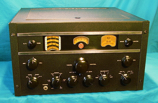
The CR-88A - post-WWII version of the AR-88F from 1947


Even in the mid-1970s, these incredible diversity receivers were still being used in RCA/RMCA stations. Parts for maintaining the aging receivers were scrounged from the WWII repair depots that had been set-up in Tangiers and San Juan, Puerto Rico during WWII. Unfortunately, most (probably all) of these incredible Triple Diversity Receivers were scrapped out with usually only the receivers themselves surviving to be sold as surplus.

With the modernized CR-88B, RCA began producing the last AR-88 version in 1951. The CR-88B, is the only variant to actually dramatically change the receiver, both in appearance and design. The CR-88B increased the tube count to fifteen, adding Push-Pull audio output. Also added was a 500kc Crystal Calibrator. Changes included a two-position Tone control, a three-position Selectivity switch and a different chassis layout that moved the power transformer forward behind the front panel. The CR-88B was in limited production until 1953 and it is the rarest of the entire series.

In the mid-1950s, the Chinese (PRC) built very close copies of the CR-88 receiver, the WS-430. The front panel nomenclature is entirely in Chinese as is the data plate attached to the receiver's chassis. Russian "octal" tubes are used in the earlier versions but later receivers were equipped with some miniature tubes. Photo in "Collector's Gallery of AR-88 Series Receivers" in Part 4 of the article.
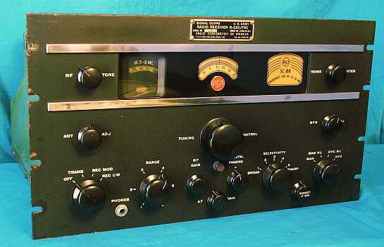

The SC-88 (aka R-320/FRC) - component receiver of OA-58A/FRC from 1950

Production level of the AR-88 series was rather high during WWII with approximately 25,000 total receivers built. After WWII, the demand was greatly reduced since the only users were commercial users and the military. The AR-88 series was never offered to the ham market and was generally not available as a new product to the average consumer. The serial numbers seem to indicate that post-WWII production was less than 10,000 total receivers and probably closer to about 5,000. This estimate brings the total AR-88 series production to around 30,000 receivers - far less than the normally quoted 100,000 (or more) receiver production.

So, what was the selling price of the AR-88? It seems to be a mystery lost in the bureaucracy of the Lend-Lease Act and later RCA commercial advertising. By comparing the AR-88 receiver to its predecessor, the AR-60 that sold for $475 in the configuration used by the USCG (the CGR-32-1,) one could estimate that the AR-88 cost at least $475 but probably somewhat more since the cost-comparison CGR-32-1 was from the late-thirties. Of course, this is just a guess. If anyone does know a specific price assigned to any of the AR-88 versions, please e-mail me and I will add that information to this article. $495 is listed as the selling price from other Internet sites but the caveat is that it's still just a guess.


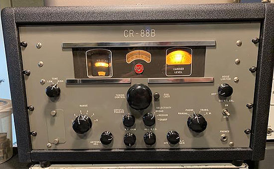
The CR-88B version of the AR-88 from 1952

photo above: This is the last of the AR-88 series, the 1951-53 CR-88B. Note the dial mask, the different placement of controls, different front panel mounting and the shorter chrome strips. Note the three position SELECTIVITY switch, 500kc CAL switch and the two position TONE switch. Inside, the "B" has push-pull audio output. This excellent condition example of this rare receiver is owned by N6YW who provided this photo (also see Collector's Gallery.)

Today, the AR-88 and its variants can be found in vintage radio ham shacks and at dedicated SWL set-ups around the world. Its global fame was earned with hard work providing great performance, reliability and durability in service. This "hard work" has resulted in many AR-88 survivors being found in rough condition, missing parts and, many times, non-functional. Fortunately, there are still plenty of enthusiasts that scavenge parts in order to perform operational restorations of these incredibly stout receivers. With fans around the world, the AR-88 and its variants are assured of continuing survival.


AR-88 Series - Circuit and Construction Details

RF Section - The AR-88 tuned from .54mc up to 32mc in six bands. It used 14 tubes in a double preselection superheterodyne circuit. The HF front end coils were wound on polystyrene forms that had extremely low losses allowing the receiver to maintain high sensitivity up to 30mc. The band switch is made up of eight ceramic switch sections with the RF coils and the band switch assemblies all mounted in two completely shielded compartments. The tuning gear reduction tuning was substantial at 100:1 and was often referred to as "continuous bandspread." A logging system using two separate dials provided accurate resetability (4400 logging index divisions available for each band - 200 divisions on logging dial and 22 logging sections on the main dial.)

IF Section - The AR-88 receivers employed three stages of 455kc IF amplification but used six IF transformers to provide 12 tuned IF circuits. The 1st and 4th IF transformers are under-coupled to provide a typical "bell curve" response at 455kc. The 2nd and 3rd IF transformers were created by interconnecting a pair of IF transformers to create a switched tertiary setup for a broad bandwidth when selecting POS. 1 and a slightly less broad bandwidth when selecting POS. 2 using the SELECTIVITY control. When POS. 1 is selected these transformers are "over-coupled" for a very broad response curve. POS. 2 provides a slightly narrower bandwidth and slightly increased gain for improved reception of weaker voice signals. To assure that the IF passband was symmetrical so the POS. 1 selectivity provided a "broad, flat top curve" usually required an "IF sweep alignment" that used of a sweep generator (Wobulator in WWII technology) and an oscilloscope for proper IF alignment (a detailed procedure was provided in later version manuals.) However, if fidelity wasn't an issue, there was a procedure to align the IF section using just a VTVM but this method usually resulted in a narrower bandwidth than if the sweep method was used. The AR-88 provided five steps of selectivity with position 1 and 2 being rather broad for good fidelity. If the IF was sweep aligned correctly then POS. 1 bandwidth should be 13kc at 3db down and POS. 2 bandwidth should be 7.5kc at 3db down. Positions 3, 4 and 5 used the crystal filter for increasingly narrower bandwidths with POS. 5 being very narrow at around 0.5kc at 3db down. The Crystal Filter phasing control on the WWII versions of the AR-88 was a located on the chassis and consisted of a C-trimmer with a slotted adjustment shaft. The Crystal Filter alignment setup assumes that the desired action would be to narrow the IF bandwidth and doesn't allow the f-nulling effect that could also be created, especially for heterodyne relief. Post-WWII versions of the AR-88 moved the phasing control to the front panel to allow more versatility to the Crystal Filter.

BFO, NL, Audio Sections - AR-88 receivers used an electrostatically coupled BFO that was connected to the input of the last IF stage to provide better performance of the BFO and less low-level signal masking in the CW mode. The electrostatic coupling was accomplished by looping the IF connection wire lead halfway around the BFO tube socket and then connecting that wire's end to an unused pin on the BFO tube socket. The AR-88 also provided an adjustable clipper-type Noise Limiter (for pulse-type noise) and a High Frequency (limiter) Tone control. The audio output was from a single 6K6 providing about 2.5 watts of power to a 2.5 ohm Z output transformer. A 600 ohm Z output was provided with rear chassis terminals using an independent winding in the output transformer. The Hi-Z phones output was derived from a tap on the 2.5Z winding. The CR-91, a Camden-built version of the Montreal-built AR-88LF, used a 6V6 as the audio output tube instead of the 6K6.


photo above
:  Cover of the WWII AR-88 Brochure

Carrier Level Meter - The various AR-88 models will sometimes be found today with a RCA Carrier Level meter incorporated into the circuit however most receivers didn't have CL meters originally installed at the time of manufacture. Initially, the RCA manuals blamed the lack of a CL meter on a shortage of meters of the specific type needed for the AR-88. Apparently, this shortage was for the entire war since the WWII AR-88 brochure states that meters "were not available for the duration." Some of the wiring for the meter was usually included in the harness for future installation of a Carrier Level meter, when they became available post-WWII. However, not all components necessary for the CL meter to function were present. Many CL meters were installed into the AR-88 receivers by the British depots and these will be British-made meters, generally with a white scale. Certainly the lack of RCA CL meters would seem to indicate that the majority of WWII AR-88 receivers equipped with proper RCA CL meters seen today had those meters installed post-WWII. It's very likely that RCA offered a CL Meter Kit for the AR-88 that included the correct meter, the necessary components, the mounting adapter and the instructions. If the CL kit was installed at a military repair depot or installed by a commercial professional, it would probably appear to be an original installation. Diversity model receivers did not incorporate a CL meter because output meters were included in the diversity rack. Post-war receivers such as the CR-88 and the CR-91A had CL meters installed as standard equipment at the time of manufacture.

photo left: The AR-88 RCA CL Meter

Power Supply Section - The receiver power supply used a potted power transformer and two potted filter chokes. The power transformer had a multi-tapped primary winding along with a rear chassis mounted voltage selector switch to allow operating the AR-88 on several different AC voltages ranging from 100vac up to 250vac. The filtering was provided by an oil-filled, paper dielectric triple capacitor unit. This multi-section capacitor along with the two filter chokes created a dual-section type of filtering that was very effective at reducing ripple and hum on the B+ line. It was also possible to operate the AR-88 on batteries using the auxiliary power socket on the rear chassis and there was also a vibrator type DC power pack available to operate the receiver from a single +6vdc source. A VT-150 was used to provide a regulated +150vdc for the LO and BFO plates and for the RF/IF screens to improve stability and reduce drift. Only the AR-88LF and the CR-91 receivers had AC line fuses that were chassis mounted. All other versions required the user to provide a fused AC line.

LF/MW Versions - The AR-88LF and CR-91 were versions with LF and MF coverage in place of the AM-BC band. Using a 735kc IF allowed continuous coverage in two tuning ranges from 70kc up to 550kc in the LF and MF part of the spectrum (Bands 1 and 2) and continuous coverage from 1.5mc up to 30mc on the remaining four tuning ranges (Band 3 through 6.) Early versions of the AR-88LF used a different power transformer with a two position AC primary voltage selector switch and a different audio output transformer that had a single tapped winding providing 2.5 ohm Z and 20 ohm Z outputs. Virtually all AR-88LFs were exported to our Allies during WWII although a small quantity remained in Canada for their military and other government uses. The CR-91 was built in Camden, NJ and the small quantity produced (about 1000 receivers) was probably to supplement Montreal's AR-88LF production. Almost all of the known CR-91 "survivors" are in countries other than the USA which indicates they were likely exported to our Allies during WWII.

Construction - Mechanically, the receivers were stoutly built. Heavy steel chassis and an almost quarter of an inch thick, copper-plated steel front panel were the foundation for component assembly mountings that were entirely put together with screws, lock washers and nuts. This was to allow extensive disassembly to be easily and quickly done, the repairs performed, followed by easy and quick reassembly. The only rivets used in the receiver are for the clips that mount the adjustment tools. Early receivers had the chassis side panels bolted in place but late receivers had the chassis side panels spot-welded to the chassis. The ultra-heavy duty construction made for a stable receiver but also added to the weight. The AR-88 weighed-in at just about 100 lbs. when installed in its cabinet. Out of the cabinet, the receiver weighed about 75 pounds and, if the bottom cover and RF cover were removed, the weight dropped to 70 pounds.


photo above: A page from the WWII AR-88 Brochure

AR-88 Series Chassis

The AR-88 chassis was almost identical for each of the various models. Shown in the four photos below is a CR-91 Camden type with a serial number of 050068 from about 1944.


The photo above shows the top of the chassis with the power transformer at the lower left and the filter capacitor pack at the lower right. The cylinder-shaped iron above the power transformer is the audio output transformer and the iron to the right of the power transformer are the filter chokes. The square choke is a replacement from a different model '88 receiver. The IF cans from left to right are the 4th IF transformer, the BFO coil, then the upper pair are the 3rd IF transformers, next pair down is the 2nd IF transformers, the next down single can is the 1st IF and the farthest down is the Crystal Filter Load coil. The four hex standoffs are for mounting the RF cover, a piece that is commonly missing on these receivers (including this one.)


The photo above shows under the chassis. The two shielded boxes contain the LO coils in the front smaller box and the Mixer, RF and Ant coils in the larger box. The switch over the IF transformers is the SELECTIVITY switch. Note that most bypass capacitors are in chassis mounted tub cans. These are oil-filled multi-unit capacitors. Note at the lower right of the chassis there is a cut-out area. This isn't original and was a "hamster mod" for a Jones connector (also SO-239 mounting holes.) This receiver was installed into a cabinet so the chassis bottom cover was not used.

Photo to the left shows the two RF boxes with their covers removed. Note that the band switch is made up of eight ceramic switch segments. Also, each compartment contains six coils with three coils on each side of the band switch in each section. Note that some of the coils are wound on polystyrene coil forms. These are only on the shortwave bands. The LF and MW coils are wound on conventional fiberboard-type forms. The long tubular components are the "plunger-type" trimmer capacitors. Note that the Antenna coils (right-most compartment) are mounted so the adjustments are accessed from the rear of the chassis.


Photo to the right is a close-up of the Antenna Coils and specifically the shortwave coils. Note that these coils are wound on polystyrene forms. The coating is mostly coil dope or lacquer to keep the coil wire wraps stationary and to protect them from moisture.

CR-88B Chassis

The CR-88B chassis was changed to allow adding the push-pull audio tubes. The power transformer was moved forward to have the receiver weight distributed more towards the center of the chassis. The AR-88s tended to be very heavy towards the rear of the chassis adding to the difficulty of rack mounting the receiver. Note that standard "can" electrolytic filter capacitors are used rather than the large oil-filled paper filter capacitor assembly. The IF transformers were reduced from eight transformers to six which implies two IF amplifier stages in the CR-88B rather than the three used in the AR-88 (it's possible that the BFO coil and Crystal Filter load coil (if used) might be mounted under the chassis which would then have six transformers providing the proper over-coupled and under-coupled IF setup.) Rear chassis connections show a "phono input" available. Also note that "AVC" and "DIODE LOAD-RETURN" terminals are provided which implies that the CR-88B could be used in a true diversity set-up. Note that the loudspeaker Z is now 3.2 ohms. The antenna input was moved to the RF tuning box.


CR-88B photos from: N6YW


Details of the Individual Receiver Versions by Model Designation


WWII Versions

AR-88 - The earliest stand-alone receiver version that may or may not have had a cabinet depending on installation. Produced in the early part of WWII, earliest versions have solid light-yellow dial (not alternating black and yellow scales) and semi-gloss smooth finish black front panel with engraved nomenclature. CL meter usually not installed at factory.

AR-88D - The later stand-alone receiver version with table top cabinet, produced during WWII and perhaps for a very short while after. Typically has a black wrinkle finish panel with white silk-screen nomenclature, sometimes with Carrier Level meter (that may have been added post-WWII,) matching speaker was available (not supplied but could be ordered.) Early AR-88D receivers had a semi-gloss smooth finish black panel with engraved nomenclature. Many AR-88D receivers had CL meters installed while in use during WWII in England. These are usually white scale, British-made meters.
Suffix "D" does NOT indicate a Diversity receiver. Suffix "F" indicates a Diversity receiver.

AR-88F - "F" is the Diversity receiver used in the RCA Triple Diversity Receivers, has IF Gain Control, no carrier level meter, rack mount only - component receiver of the DR-89 and RDM Triple Diversity Receivers, typically black wrinkle finish panel, white silk-screened nomenclature.

AR-88LF - Stand-alone receiver early LF/MF version with 70kc to 550kc coverage and 1.5mc to 30mc coverage, earliest versions had a two position AC voltage selector (115/230vac,) different (from AR-88D) power transformer, different audio transformer, different phone jack operation (no load resistor,) changed after SN 3000 to use same power supply and audio section components as in AR-88D. All AR-88LF versions were assembled in Montreal. Early versions have semi-gloss black panel and engraved nomenclature while later versions have black wrinkle panel with white silk-screened nomenclature. Usually had a metal data plate on front panel.
 
CR-91 - RCA-Camden version of the AR-88LF. Stand-alone receiver, late-WWII version with table top cabinet, black wrinkle finish panel with white silk-screened nomenclature with "PHONE" and "BFO" on the Function switch rather than "REC MOD" and "REC CW." Cabinet also black wrinkle finish. The CR-91 uses a 6V6 as the audio output tube (all other AR-88 versions use a 6K6 audio output tube.) The CR-91 receivers were probably produced to supplement Montreal's AR-88LF production with most receivers sent overseas.

CRV-46246A - Navy designation for the AR-88F, a component receiver for the Navy triple diversity RDM receiver. Usually had a metal data plate tag mounted to the front panel with identification and RDM reference. Early versions may have had semi-gloss black front panels and engraved nomenclature.

Post-WWII Versions


CR-88 - Stand-alone receiver, post-WWII Military/Commercial version of AR-88D, Crystal Filter Phasing control mounted on the front panel, cabinet mounted, CL meter was standard equipment, standard finish was smooth RCA Umber panel, gray plastic dial panel and wrinkle finish cabinet in matching color. Different knob sizes used when compared to AR-88 models with RF, AF and Phasing knobs reduced in size to allow the three controls to be clustered together under the main tuning knob. ANT ADJ and BFO knobs also reduced size.

CR-88A - Post-WWII diversity receiver with IF Gain control, standard finish was RCA umber panel, gray plastic dial panel, no CL meter, used in later versions of RDM and DR-89. Sometimes encountered mounted in matching cabinet as stand-alone receiver but the authenticity of such a combination can't be confirmed.

CR-91A - Post-WWII upgraded version with front panel Crystal Filter Phasing, CL meter, RCA Umber panel, gray plastic dial panel, other post-WWII upgrades. Successor to AR-88LF with ALL versions built in Montreal, Quebec, Canada for the Canadian military and commercial users. Typically rack mounted but possibly supplied with cabinet depending on end user.

CRV-46246B - Navy designation for the later CR-88A version for the later RDM triple diversity receiver, usually this number is on a metal tag mounted to the front panel along with RDM reference. Front panel crystal filter phasing control.

R-320/FRC - Signal Corps designation of the SC-88 diversity receiver version for the Signal Corps OA-58A/FRC triple diversity receiver, with dial mask, black ultra-fine finish wrinkle panel, black plastic dial panel, rack-mounted only - if found mounted in a table cabinet it isn't an authentic combination. 1950 contract.

SC-88 - RCA designation of the Signal Corps R-320/FRC. Other changes included replacement of the plunger-type trimmer capacitors in the front end and rearrangement of many of the RF alignment adjustments. 455kc crystal mounted on top of the chassis. Typically, receivers will be MFP treated.

CR-88B - Upgraded stand-alone receiver with many changes including P-P audio, 15 tubes, dial mask, crystal calibrator, 3 position selectivity, 2 position tone switch, RCA Umber panel, gray plastic dial panel, shorter chrome strips, cabinet, matching loudspeaker available, last version produced 1951 to 1953.

NOTE: RCA-Camden and RCA-Montreal could and would do special finishes upon request, if possible. There are many examples around that are too numerous to list. If it looks original and is a professional quality job, it probably is original. Military depot echelon-5 level reworks might have been responsible in some cases. The non-typical finish must be a good professional quality job and should "make sense" to be considered original (and even then it's a "maybe.") 

 
The Diversity Receivers - General Information - Many of the AR-88 receivers were used in Triple Diversity Receivers like the DR-89 - a seven foot tall rack loaded with three AR-88F receivers and all of the auxiliary equipment necessary for professional diversity reception. The DR-89 was initially produced during the latter part of WWII. As with the single AR-88 receivers, DR-89s were sent to our Allies during WWII as part of the Lend-Lease Act of 1941. The US Navy also used the diversity receivers with the designation of RDM. The receivers used in the DR-89/RDM are slightly different from the standard "stand alone" receiver. For instance, even if meters had been available, the Diversity AR-88 receivers would not have Carrier Level meters installed because the Diode Load from each receiver was connected to the Tone Keyer of the DR-89/RDM rack where the signal was then routed to the Monitoring Unit which contained three Output Level Current Meters, one for each receiver. All AR-88 receivers (and their variations, e.g., CR-88A) that were intended for use in the RCA Triple Diversity Receivers had a "DIVERSITY IF GAIN" control on the front panel for balancing the three receivers in the rack  This provided a method of adjustment for equal diversity effect (referencing the desired signal or a calibration signal) even if the receivers and antennas were not exactly identical in their performance. There were some resistor changes in the IF section to enhance diversity and AVC characteristics. The U.S. Army Signal Corps had their versions of the Triple Diversity DR-89 with the Signal Corps ID of OA-58A/FRC. These diversity set-ups used a different, upgraded receiver, the SC-88.

Not all Diversity Receivers were used exclusively in the Triple Diversity Receivers, however. Shown in the photo right is the RCAF listening station #5 Radio Unit at Whitehorse, YK, Canada from the 1950s showing the CR-88A "diversity" version receiver used along with the Hammarlund SP-600 JX receiver. Note that the CR-88 has the "Diversity IF Gain" control which identifies the receiver as a Diversity model (no CL meter either.) When operated as individual receivers, a diversity receiver's performance will be identical to standard non-diversity receivers.  >>>    


More Details on the "Triple Diversity Receivers" in Part 2 of this article.


>>>  But, it doesn't seem likely that RCA would have supplied Diversity models for stand alone receiver applications. However, there is some evidence of CR-88A receivers being installed in correct cabinets that appear to be original combinations. Unfortunately, it's possible that an end user could have performed such a modification at anytime during the receiver's existence. Even in the photograph above one has to consider that the CR-88A was probably already a "used" ten year old receiver when installed with the SP-600 JX receiver.     photo above from:  www.jproc.ca


More Detailed Information About the AR-88 Receivers

Front Panel Colors and Cabinets - The first AR-88 receivers had smooth finish, semi-gloss black painted front panels with engraved nomenclature that was white paint filled, as shown in the photo to the right of AR-88 SN:005112. ALL of these early receivers were destined for overseas use and are very rarely encountered in the USA. Since the engraving might have actually been stamped into the steel panel, the finish on these panels had to be smooth paint because it's virtually impossible to paint fill engraving on a wrinkle-finish panel. It's likely that only the early AR-88 and AR-88LF and possibly Navy RDM CRV-46246A receivers will be found with smooth finish painted panels with engraved nomenclature.

As production evolved, the standard panel finish became black wrinkle paint with white silk-screened nomenclature. From late-WWII on (ca. 1944,) all AR-88 panels have silk-screened nomenclature. It's been reported that some of the AR-88F receivers that were used in the Navy RDM receivers had smooth gloss finish black panels thought that's not confirmed by actual surviving examples. The majority of RDM/AR-88F receivers and associated equipment had black wrinkle panels.

After WWII, RCA Umber (light brownish-gray) panels started to be produced. The plastic panel that covers the dials was changed to dark gray when installed on the umber panel receivers and remained black when installed on black panel receivers. Most of the CR-88 versions have smooth finish umber panels but there are always some exceptions. The RCA "umber" finishes actually have quite a bit of brown mixed in giving the panel a distinctive brownish-gray look (see CR-88A photo above in "History" section.)

RCA also produced a darker brown wrinkle finish version of the AR-88 that was probably for their own broadcast installations (RCA may have also used this finish on CR-88 receivers in the same broadcast application.) The Royal Canadian Air Force (and possibly the RAF) had some of their AR-88 receiver panels finished in smooth gloss finish dark blue although with engraved panels an end-user repaint is the most likely source of these blue panel receivers.  >>>


photo above
: AR-88D SN:005112 showing the smooth finish semi-gloss black paint panel with engraved nomenclature.  photo from: W3TA
 

>>> There are many other colors that show up from time to time, especially cream and very light gray both with black nomenclature, but without a physical inspection it is impossible to tell if those colors are original from the factory. Silk screened nomenclature would generally confirm originality of the panel paint.

There are also reports of a black bakelite panel used on an AR-88, though this would have presented several electro-mechanical issues to deal with. More than likely the report of a bakelite panel stemmed from an erroneous identification of the gloss black panels used on some RDM component receivers or the early engraved nomenclature panels. Factory original panels seem to all be various colors of paint over copper-plated steel with silk-screened nomenclature (with the exception of early WWII production that had engraved nomenclature rather than silk-screened.)

Cabinets - Original cabinets are somewhat rare and are usually black wrinkle finish however brown and "RCA umber" cabinets do turn up and the AR-88 that was original dark brown wrinkle also had a matching dark brown wrinkle finish cabinet. Since the AR-88 chassis is 17" deep very few cabinets other than originals will work. The only fairly "easy to find" cabinet is the type used on the WWII Scott Radio Laboratories SLR receivers. A little cutting in the rear is required for the Scott SLR cabinet to work but it is deep enough (the cutting is for clearance that is needed for the AR-88 AC Voltage selector switch.) The Navy RCH receiver cabinet will also work.

Power Supply - The power transformer is robust and a potted unit that seldom has any problems. The primary has five taps that are routed to a rear panel switch that selects the proper AC operating voltage. The AC line is not fused on any of the receiver versions except the AR-88F and the CR-91. Two filter chokes are used. Some British magazine articles suggest that very early AR-88s had two different types of chokes. It's reported that the choke's dc resistance was 400 ohms for L-49 and 800 ohms for L-50. However, every manual and parts list I've seen indicates that the two chokes are identical, each with 400 ohms dc resistance. Actual measurements of the chokes in various AR-88s I've had access to show the same result - that both chokes are identical. It's normal for L-50 to run slightly warmer than L-49, especially if the receiver has all original capacitors. The filter capacitor housings change over the years with early receivers using an oil filled, three capacitor pack. Later versions have three individual oil filled capacitors with two capacitors on top of the chassis and one capacitor underneath.
Manuals and Documentation - Like most RCA products of the forties and fifties, documentation is very good on the AR-88 series. There are minor errors in some of the early manuals - like two R50 resistors shown in the under-chassis component view - but, overall the documentation is easy to find and accurate. Original RCA manuals are high-quality publications with heavy covers. The figure drawings are very clear. There are some British Military manuals available that give excellent information and also a slightly different approach to alignment. Almost all of the documentation is available online at the BAMA edebris website. The exception is the R-320/FRC (SC-88) manual, TM 11-899. Fortunately, this is available from Fair Radio Sales. None of the early AR-88 series manuals provide detailed wiring diagrams which are different from schematics and are helpful in locating specific component placement or wire routing. The CR-88 (and later) manuals do provide some wiring diagrams. On early receivers, one has to use the schematic and component location drawings to figure out the correct wire routing and correct component locations. This is only a problem in receivers that have been modified or compromised by poor repair techniques over the years and need to be returned to their original configuration. Antenna Input Connections - The AR-88 receivers that were intended for surveillance or intercept work are connected up and operate much like any other vintage communications receiver. The Antenna Input Z is 200 ohms but the receivers have an Antenna Trim control that allows a wide variety of antennas to perform well with the receiver. Band 1 (AM BC) was designed to work well with an end-fed wire antenna but on the higher frequencies, a matched antenna will give the best results and use of a separate antenna coupler will provide the receiver with the best match to any antenna. The AR-88LF and CR-91 receivers were designed for a capacitive antenna on Bands 1 and 2, which cover the LF and MF frequencies. Anywhere from 500pf  to 700pf works fine and can be accomplished with an end-fed antenna around 200 feet in length. Shorter antennas will detune the 1RF amplifier unless capacitively loaded.
Tuning and Logging Dials - The very first AR-88 tuning dials were solid light-yellow with black nomenclature. These dials were used probably up to about serial number 3000. By mid-WWII production, the tuning dials became alternating black and light-yellow backgrounds with the nomenclature oppositely alternating accordingly. After that, all versions used the black and yellow "striped" dial until the dial mask was fitted to the SC-88 and the CR-88B. These receivers went back to the solid light-yellow dial with black nomenclature. The dial color we see today on the AR-88 receivers is much darker than original. The darkening is especially intense where the dial was exposed to sunlight. This usually resulted in portions of the dial appearing very dark amber and other sections appearing orange or yellow. Original color was very light pale yellow. Post-WWII, RCA-Montreal did produce some CR-91A receivers for certain end-users that were fitted with a white tuning dial, white logging dial and white CL meter scale. Two examples have been reported with a photograph of one receiver shown in the "Collector's Gallery" in Part 4. One receiver, SN C241M, was used by the Royal Canadian Air Force.


photo right: F1JGC, Lucien, owns a very early AR-88 with the serial number of 002385. Of particular interest is the all-yellow tuning dial which was only used on the early production receivers. By the end of WWII, the receivers produced had the alternating black and yellow scales on the tuning dial. Lucien has started restoring this receiver. (Also, note the AR-88 dial in the G5FA QSL photo in a section above.)

Tuning Dial Resolution - The AR-88 receivers have what was called "continuous bandspread" action, which was a 100:1 gear reduction in the tuning that resulted in an almost vernier effect for tuning in stations. Since the AR-88 covers large slices of the spectrum in each tuning range, the tuning dial resolution is necessarily vague. When the AR-88s were in active use and the received frequency had to be accurately known (or set,) it was measured with a heterodyne frequency meter - all military and commercial stations had them when frequency accuracy was mandatory. The Logging Dial then provided a very accurate way to reset to exact frequencies once their relationship to the logging dial was known. 4400 index divisions were available on each band for exact logging and frequency resetability. This consisted of 200 divisions on the logging dial and 22 logging sections on the main dial. Tuning and Logging Dial Positions - If the AR-88 front panel is removed, it will be noted that the two dials over-lap each other and it's possible to have either the logging dial in front of the main dial or behind it. If the receiver is the older style with the metal frame holder for the dial index then normally the logging dial should be placed behind the main dial. This assures that there is ample clearance for both dials to not interfere with each other and to also assure that the logging dial index doesn't rub against the logging dial hub. Later receivers with the plastic index usually have the logging dial in front of the main dial since the logging dial can be placed very close to the plastic index without rubbing. This latter positioning is also required on SC-88 and CR-88B receivers because of the dial mask installation. CRV-46246A/B (RDM) Receiver 2.5 Ohm Z Output - These component receivers for the RDM were designed to work within the Triple Diversity Receiver rack. Specifically to connect the 2.5 ohm audio output terminals to the Tone Keyer input. Terminal 2 on the receiver is not grounded but achieves its ground inside the Tone Keyer. This was then switch routed to the Speaker Panel where the operator could select individual receiver outputs or the diversity output. Probably most CRV-46246A/B receivers have long since been modified to internally have Terminal 2 connected to the receiver chassis to allow the receiver to operate as a "stand-alone" receiver. However, it's possible a few receivers are still out there with the Terminal 2 ungrounded at the receiver. The ungrounded Terminal 2 may also apply to the commercial version AR-88F receiver. Later diversity receivers, CR-88A and SC-88, have Terminal 2 grounded at the receiver.
2.5 Z Ohm Output and 600 Z Ohm Output - The required speaker impedance for the AR-88 is rather low at 2.5 Z ohms to 3.2 Z ohms. Today it is pretty hard to find a 2.5 Z ohm speaker and the original AR-88 table speakers MI-8303D are quite rare (voice coil was 2.2 Z ohms at 400hz.) The 3.2 Z ohm speakers are fairly easy to find and work quite well with the AR-88. I have also found that the standard 4 Z ohm speakers work fine and allow a lot more choices for quality speaker selection. Using a 12" speaker in a floor cabinet with a bass reflex port will provide you with the excellent audio reproduction that the AR-88 is capable of. Lots of bass and, if aligned correctly, plenty of highs in the BROAD position. Using an 8 Z ohm (or higher) speaker will require the AF gain to be advanced a bit further than with the lower Z speakers. The lower Z speakers sound best. The 600 Z ohm impedance line output was provided to drive various external devices and is a completely independent winding. If the 600 Z ohm winding isn't used then a 680 ohm 1/2W CC resistor should be connected across the terminals as a load. NOTE: If you want to use the 600 Z ohm winding to drive a loudspeaker and don't intend to use the 2.5 Z ohm terminals then a 4.7 ohm 2W CC resistor should be connected across the 2.5 Z ohm terminals for a load. You can also use a "dummy" phone plug inserted all the way into the PHONES jack to connect the internal 5 ohm load resistor. Either method will load the 2.5 Z ohm winding and will improve the sound quality of the 600 Z ohm line audio.


MI-8303D Loudspeaker


RCA Table Speaker for the AR-88D and CR-91 - When the receiver was intended for table top operation a matching speaker was available from RCA. It was listed as part number MI-8303D. The original speaker was an eight inch diameter PM type that had a 2.2 Z ohm (at 400hz) voice coil to match the output Z of the AR-88. The speaker cabinet was usually black or RCA umber wrinkle finish and the grille was nickel-plated. There are some photos that show the speaker grille where it appears painted but the RCA manuals always pictured the plated grille. The speaker cabinet has a back that is screw mounted and that is why the speaker cable exits from the side.  The MI-8303D was shown in the AR-77 brochure as the matching accessory loudspeaker with a selling price of $8.00 (1940.) The loudspeaker was redesigned for the CR-88B and has a very different appearance.

An Alternate Loudspeaker - There's another loudspeaker that, while not less expensive than the MI-8303D, is much easier to find and uses a 3.2 Z ohm voice coil. The Collins 270G-1 loudspeaker is generally shown as a 4.0 Z voice coil but I've measured mine and it is actually 3.2 Z and it is the original loudspeaker. I used a Raymer LTS-1 that is specifically designed for measuring loudspeaker voice coil impedance.


photo above:
Original RCA component AR-88 CL Meter from EB5AVG's AR-88D receiver. This is the RCA meter and shows the -6 to 0 to +100db scale with the "DB ABOVE 1 MICROVOLT" indication. The meter scale was originally a pale tan to light yellowish color. Most scales have darkened considerably from the original color.
   
Photo by: EB5AVG
AR-88 Carrier Level Meter - Ambiguous Originality - Very few early AR-88 receivers had an original carrier level meter installed. At first, since practically all signal intercept was listening in the CW mode and since a CL meter is virtually useless in that mode, no meters were necessary. Later, the RCA manuals claimed that it was the "WWII meter shortage" that was responsible and the AR-88 brochure printed during WWII states "meters not available for the duration." The manual further states that when meters became available they could be installed since the wiring was in the harness. This was only partially true, some of the wiring was present but not all of the required components were and some components in the receiver also needed to be changed. The meter mounting hardware or bracket wasn't included either. Then, also during WWII, some of the RCA production of AR-88 series receivers were for diversity receivers where the carrier level meter was not required since the three CL meters for the three receivers were installed in the Monitor Unit position of the diversity rack. As a result, only a handful of CL meters were ever factory original RCA installations at the time of construction of any WWII AR-88 receiver. This, of course, leads one to the conclusion that most CL meters installed in WWII AR-88 receivers were installed post-WWII. It's probable that RCA offered a meter installation "kit" for the AR-88 that included the meter, components and instructions necessary for the CL meter installation. If that installation was done at a military depot or by commercial professional it would certainly look very close to an original, WWII production job. The fact that original RCA AR-88 meters sometimes are found still in the original box tends to support the post-war "CL meter kit" scenario.

While the AR-88 receivers were being used in England during WWII many of the receivers had CL meters installed by the British depots. These are usually a white meter scale type of British-made meter. Additionally, there's usually a black bakelite type of connector on the rear chassis that connects the AVC line to the CL meter. While these meters are certainly period installations and well-worth keeping installed in the receiver because of the history, these aren't the RCA type meter and the installation doesn't follow the RCA circuit for a CL meter. 

The meter, when an original RCA supplied component, is a right-hand mechanical zero with full scale deflection (one division over -6db) requiring 5mA of current flow through the meter coil. The meter scale is -6 to 0 to +100 db and also on the scale is marked "DB ABOVE 1 MICROVOLT" The meter is illuminated and the scale is light yellowish-tan color. As mentioned, only some of the carrier level meter wiring was included and some of the early production receivers will have the two meter wires with their terminals bolted to the rear of the lamp bracket for the receiver ID plate. By the time the CR-88 and the CR-91A were being produced (post-WWII) CL meters were standard equipment. The exceptions are the CR-88A and the SC-88 which were Diversity Receivers.

CL Meter Circuit - The schematic shown to the right is for the CL meter connections. It shows the resistor changes necessary and must be also referenced to the receiver schematic too. Unfortunately, you can't just connect the couple of wires provided and expect the CL meter to work. R21 is the 100 ohm potentiometer that will have to be mounted on the rear chassis apron (there's a mounting hole provided for it - usually.) The rest of the circuitry shown to the right must also be installed.

R20 shown is the already present 100 ohm Cathode resistor on V5 connected to pin 5 (shown as K1 because there are two pins connected to the Cathode and the Suppressor grid in the 6SG7.) Resistors R1 and R6 are in the receiver and must be changed. They are the Screen load resistors for the RF1 and RF2 amplifier tubes. They are changed from 33K to 47K.

R55 is the series IR resistor for the RF Gain pot and that is changed from a 6800 ohm resistor to a 5600 ohm resistor.

Components added are C74 4700pf (across the meter terminals,) M1 - the meter as described above and R21 - the 100 ohm pot - also described above.

As can be seen in the schematic, the CL meter is measuring cathode current of the 1st IF amplifier tube. When in AVC, the signal strength will determine the AVC voltage which in turn determines the grid bias of each AVC controlled stage within the receiver. Strong signals increase the negative AVC bias voltage which reduces V5's cathode current and reduces the CL meter deflection and moves the meter needle to the right which indicates a stronger signal.

Crystal Filter Crystals - For some reason many AR-88s will have had the crystal filter's crystal removed. On the last models this might be understandable since the crystal plugs into a socket on top of the chassis. But the early versions have the crystal hard-wired underneath the chassis and, yet still, sometimes they will be missing. Fortunately, the 455.00 Khz crystal is available from International Crystal Manufacturing in OKC, OK (not anymore,...Intn'l Xtal out of business 2020.) The 455.00 Khz crystal is a stock item and the cost is $25.00. If you need the 735 Khz crystal for the AR-88LF or CR-91, that one has to be special ordered from ICM. They will make one for you but as custom work, they are not cheap - $109.00. Remember, they have to grind the crystal and the low frequency crystals do require a different cut from the quartz, thus the expense. Custom frequency crystals are becoming extremely difficult to obtain. They can be ordered from the UK but turn-around time is quite long. Used (reground) crystals are another option but they are in FT243 or similar holders. Another possibility is to find a good crystal from an AR-88 or AR-88LF/CR-91 "parts set." - 2021. Diversity Receivers versus Standard Receivers - The AR-88F, CR-88A and the SC-88 receivers are slightly different receivers from the standard AR-88D, AR-88LF and CR-91 and other non-diversity receivers. Several resistor values are changed and some extra components added to enhance diversity operation. As individual receivers both types perform almost identically. All diversity receivers were normally rack mounted although there were certainly some exceptions, especially after WWII. Though the Standard Receivers do provide the AVC line output on a terminal marked "AVC" and this can be coupled to another standard receiver's AVC line, this only provides a crude form of diversity effect. In this type of diversity reception, the receiver with the strongest signal controls the AVC line and the gain of all of the receivers. This does work to control fading to a certain limit determined by the AVC delay and antenna types used. True diversity reception requires the detectors of each receiver to be tied together as the Diode Load and the AVC lines tied together for diversity system stability. When working on either a standard receiver or a diversity version of the AR-88 series be sure to use the correct schematic since there are several subtle differences between the receivers.
The Diversity IF Gain Control - This control is normally only on the component receivers used in the RCA Triple Diversity Receivers - the DR-89, the Navy RDM and the Signal Corps OA-58A/FRC. This control adjusts the gain through the IF section of the receivers by using a variable resistance in the cathode circuit of the 1st and 2nd IF amplifiers. The Diversity IF Gain control allowed the operator to "balance" the three receivers in the rack using a test signal (usually the incoming signal.) Once adjusted, each of the three receivers responding with the same gain to the same signal which further enhanced the diversity effect. When the receivers are operated individually, the Diversity IF Gain can be advanced fully. Apparently, later in production, the Diversity receivers were sometimes sold as individual receiver to certain customers. Consequently, some Diversity receivers might be found mounted in the proper RCA AR-88 cabinet as an original combination. Diversity, Monitor, Diode Load and Diode Return Connections - These connections on the rear terminal strip are only on the component receivers of the RCA Triple Diversity Receivers. When operating in diversity, it is necessary to have all of the second detectors outputs tied together which is done through the "Diode Load" and "Diode Return" connections. Additionally, the AVC lines from each receiver are tied together via the "Diversity" terminal. These receivers can be operated as a stand-alone receiver but it will be necessary to jumper the "Diode Load" and "Diode Return" terminals together. No connections to the "Diversity" terminal or the "Monitor" output are necessary for individual receiver operation.
Tuning Gear Box Variations - There are two types of gear boxes found on the AR-88 series of receivers. The most commonly found gear box is "Version One" (V-1) that, fortunately, is the most robust and problem-free type. The V-1 gear box is found on all of the AR-88 series receivers except for the CR-91A. V-1 gear boxes will have a 360º split-gear that is spring-coupled and mounted to the hub of the tuning condenser drive gear. This split-gear drives the main tuning dial as the tuning condenser drive gear rotates. The fact that the split-gear is a full 360º piece adds to its overall strength. The V-1 gear box seldom has any problems other than the normal dirt and dust accumulation and occasionally an over-tight bearing adjustment.

"Version Two" (V-2) gear boxes are only found on the CR-91A receivers, all of which were built in Montreal. The V-2 gear box has a 270º split-gear that is spring-coupled to drive the main tuning dial from the rotation of the tuning condenser drive gear. Since the V-2 split-gear is not a complete "circle" (not 360º) it's not nearly as strong as the full 360º split-gear in the V-1 gear boxes. The V-2 split-gear is prone to breaking teeth off of the gear that will result in erratic tuning dial operation. Of two V-2 gear boxes examined, both had broken teeth on the split-gear and neither gear box operated the main tuning dial smoothly. Since only two CR-91A gear boxes have been examined, it isn't known if all CR-91A receivers built had the V-2 gear box installed. It's likely that the V-2 gear box was considered a design "improvement" and may only be found on the later versions of the CR-91A.

At present, I have examined an AR-88, CR-88A, CR-91 (Camden version) and an SC-88. All of these receivers have the V-1 gear box installed. Note that the SC-88 is from 1950 and is one of the last versions of the AR-88 receiver built in the USA and it's using a V-1 gear box. The two CR-91A gear boxes were obtained from VE8NSD and were "pulled parts" from Canadian government surplus purchased CR-91A receivers. The conclusion is that the V-2 gear box will only be found on some versions of the CR-91A receiver.

photo left: "Version One" (V-1) of the gear box showing the full 360º split-gear that drives the main tuning dial. Note that the split-gear is mounted to the hub of the tuning condenser drive gear which appears to take up most of the lower part of the photo and is fairly reflective. The split-gear engages a gear that is mounted on the end of the shaft that drives the main tuning dial. Also, note that the anti-backlash spring is a loop type coupling the two split-gears (not visible in the photo - the upper gear is slotted to allow the spring-end to be moveable.)

photo right: "Version Two" (V-2) of the gear box showing the 270º split gear that is not as robust and prone to failure. Note that these split gears are coupled using a coil spring type of anti-backlash arrangement. It can be seen that the split-gear is not as closely coupled and this may account for its tendency to break some of the gear teeth.

Operating with Missing Shields - Many AR-88s are nowadays missing the bottom cover, the RF cover and some are even missing the tuning condenser cover. If the receiver was installed in a cabinet, such as the AR-88D or CR-91 were, then the bottom cover was not usually installed since the cabinet acted as the bottom shield. Additionally, the LO and Mixer/RF coil boxes are fully shielded, so the bottom cover is more for component protection than anything else. The receiver seems to operate fine with the RF cover off or missing, too. Its main purpose was to protect the alignment adjustments. The condenser cover should be in place for protection of the tuning condenser but a great many are missing and the receiver's performance doesn't seem to suffer with it off (alignment may suffer slightly.)

Originally, the extensive use of shielding was to prevent LO radiation from coupling into the antenna. The Navy and FCC specification was less than 400pW at the receiver's antenna terminals. This then allowed the receiver to operate in the present of other receivers and transmitters without causing interference or being interfered with. Also, if excessive LO radiation made it to the antenna, it was theoretically possible for enemy Direction Finding equipment to pinpoint the receiver's location.

Today, many AR-88s are operated in the ham shack with some of the shields missing with no serious issues. If the AR-88 receiver is operated with an electronic T-R switch in the Voice mode, audio feedback will be encountered in "transmit." Normally, when using the AR-88 in the ham shack, it is necessary to reduce the RF and AF gain controls during "transmit" to prevent feedback even if all of the shields are installed and the receiver is in a cabinet.

"TRANS" Relay Control in NON-Diversity Receivers - This function operates in conjunction with terminals 3 and 4 on the rear of the chassis that are marked "TRANS RELAY." RCA, during the design of the AR-88, decided that the receiver should be controlling the transmitter and so the "TRANS" position of the function switch shorts terminals 3 and 4 when selected. Unfortunately, receiver control of transmission is the opposite of today's normal transmitter control of ham station's  "Send-Receive" operations. Though it is possible to have an AR-88 actuate the remote Push-to-Talk line, allowing the AR-88 to control the "Send-Receive" operation, many transmitters don't have the PTT line brought out as a "remote" function. The easiest solution, if your mode of operation is CW, is to operate the station using an electronic TR switch such as the type made by E.F. Johnson. This allows the receiver to be left on while transmitting and the electronic TR switch will protect the receiver input. In the Voice mode, a TR switch will "feedback" unless 'phones are used. You'll still hear yourself in the 'phones though. A method of muting the AR-88 receivers is shown in the section "An Easy and Reversible Muting Mod for the AR-88" write-up is located in Part 4.

See section "Operational and Modification Caveats" below for possible problems that can develop when the receiver is in the "TRANS" position.

Additional Note:  On some versions of the Diversity receivers, the two wires from the FUNCTION switch that provide a closure when selecting "TRANS" are included in the wiring harness and are both soldered to Terminal 2. In early Diversity receivers, the 2.5 ohm Z audio ground was not provided by Terminal 2 but was achieved via the Tone Keyer. RCA decided to attach the "TRANS" wires from the harness to this terminal since it was going to be grounded in normal rack wiring and operation.

CONTINUE TO PART 2


AR-88 Part 3                             AR-88 Part 4                           Return to Home Index


Radio Boulevard
Western Historic Radio Museum

 Vintage Radio Communication Equipment Rebuilding & Restoration Articles,

 Vintage Radio History and WHRM Radio Photo Galleries

1909 - 1969

- 60 years of Radio Technology -


This website created and maintained by: Henry Rogers - Radio Boulevard, Western Historic Radio Museum © 1997/2023