|
The 2021
Wells Gardner & Co. RAO-3 Restoration
The almost impossible to solve problem of
missing data plates on my old RAO-3 suddenly became solvable when a
"parts set" RAO-3 with data plates showed up on eBay. A close
examination of the photographs revealed that not only were the
data plates present but almost ALL of the non-original or
compromised parts that were
present on my old RAO were original and present on this parts
set. Having owned my old RAO-3 for over fifty years and having
repaired it a couple of times in the 1969-1970s time frame along
with a major cosmetic restoration in 2006, I now had the
opportunity to actually perform a complete restoration of the receiver and have it not
only look like a good condition original but "up the level" of
restoration to "museum quality" with a total electronic rebuild.
There's nothing better than having a good, useable "parts set"
for a restoration project. This restoration will allow the receiver to function correctly for long time
periods as
originally intended and to perform ideally as a vintage military
receiver in an amateur vintage military radio station. |
|
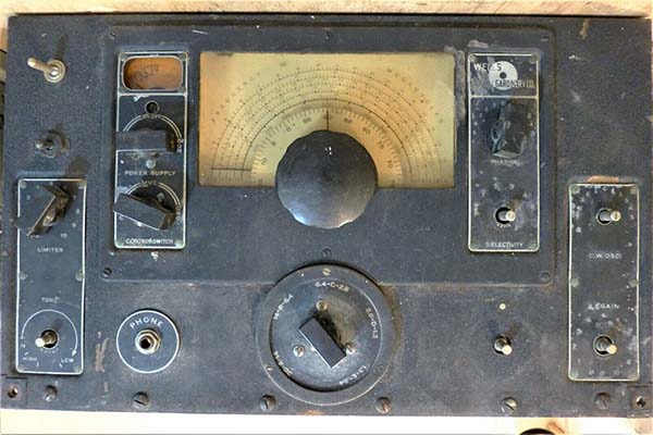
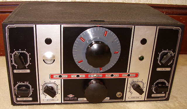
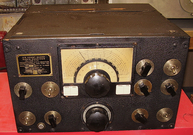
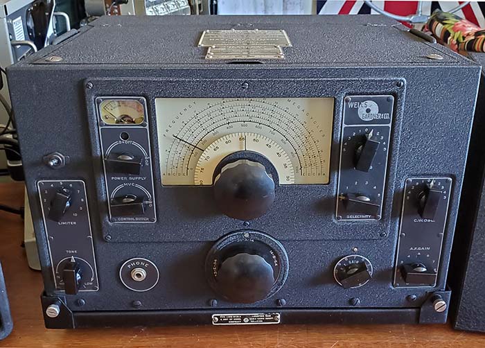
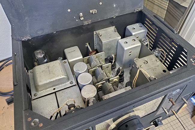
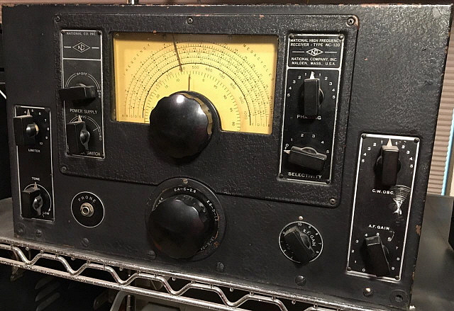
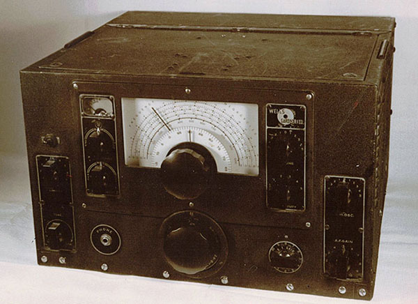
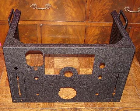
photo above: The eBay photo of the "parts
set" RAO-3 |
January 9, 2021 - I
happened onto an eBay listing of a "needing restoration" RAO-3. What was
interesting was this receiver had all of its data plates. I had never
come across a RAO-3 that still had its data plates installed and I actually
thought that the reason might be that Wells Gardner had dumped a lot of receivers
(that
hadn't been used to fulfill contracts) onto the surplus market,
naturally without tags. In
addition to the data plates, this RAO had the original audio output
transformer, the original WG power transformer cover, the original dial
lamp sockets and harnesses and the original cover for the first RF
amplifier tube with retaining nuts. Additionally, all of IF transformer
cans still had the silk screened identifications. The receiver chassis
inner threaded metal pieces for the shock mount thumbscrews were
present. Besides the overall "rough condition," what probably made the
receiver a "parts set" was about half of the knobs were gone and the bottom cover
was missing
(parts I didn't need.) Also, a hamster mod had added a toggle
switch to the left of the S-meter ruining the front panel. The really "good" thing was the
seller was located only about 450 miles away (The Sisters, Oregon) so FedEX
Ground shipping wasn't too expensive. The auction was won ($59) and in
preparation of the restoration, my old RAO-3 was extracted from the shop
storage and brought upstairs for testing.
"Parts Set RAO-3" Inspection -
Arrived Jan. 15, 2021 - Good data plates, good audio output transformer, all
four threaded adapters for the shock mount are present, first RF amp
housing cover present, original power transformer cover present, almost
all of the silk-screened identifications are present on chassis
components.
Unfortunately, the Antenna input was a hamster'd RCA phono jack. The
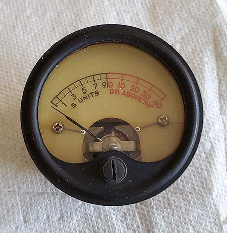
S-meter scale was the typical "no red" faded and darkened plastic. AF Gain pot was a later replacement part and it was
an incorrect linear taper type pot. Should be an audio taper. A check in
my spares "pot box" turned up four 500K audio taper pots, so no
problem. Overall, 95% of the parts needed were present and in good
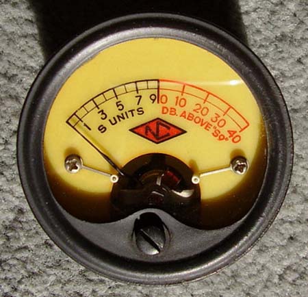
condition. I had an original Navy coax receptacle and I had an original NOS Marion Electric
"for Wells Gardner RAO" S-meter to use in this restoration. |
|
The "Old RAO-3" Quick Test - I'm not
really sure if I'd applied power to the old RAO-3 since the 2006 "on the
air" testing which took place in Virginia City. Since that time there
had been a move to Dayton and further storage. Sometime in the past 14
years, I did pick up a correct and original RAO-3 shock mount for the
receiver but I don't remember operating the receiver at that time, just
mounting it to the shock mount and photographing it. Well,...fourteen
years of storage did require a slight bit of prep before the power up. I
needed an AC power cable. I had always used some type of hamster power
cord that would have a molded end that could be forced into the
"twist-lock" AC receptacle. This time I made up a "correct" power cable
with the proper twist-lock plug, an excellent condition vintage power
cable and vintage AC plug. After that, a 600Z ohm speaker was plugged
into the PHONE jack (Hmmm,....I guess I got ahead of myself and forgot that I still had
the replacement 8Z audio transformer in this RAO receiver, oh well,...)
A ten foot long test wire antenna connected and, using a Variac,
I ramped up the AC input voltage to 115vac in about 15 seconds. The AC line
here is 122vac, so the Variac lets me adjust the input voltage to the original spec
of 115vac. The receiver audio reproduced lots of ambient background noise and a few ham
signals on 40M. I disconnected the 10 foot wire and attached the 135'
Tuned Inv-Vee ham antenna. Big boost in signals and lots of 40M activity.
With the CWO on, I tuned
some higher frequencies for testing and I found HLO, a Korean Frequency Marker
Beacon around 12.9mc besides all of the normal SW BC in the 25M band. Sensitivity seemed reasonable but the following
problems were noted,... 1. The Crystal Filter although somewhat
working didn't really seem to have a variable narrow notch. Might be alignment but could also be a crystal
problem.
2. Any slight change in the RF Gain would cause a significant change in
BFO frequency. This is a common problem in "original 75+ year old
components" HRO and NC-100 receivers.
3. A slight hum was noticed in the loudspeaker if listened to in close
proximity. Could be many things. The filter caps are oil-filled paper
dielectric.
4. Wrong tube in the audio output - had a 6V6 installed, should be a
6K6. 6V6 is a beam-power pentode while the 6K6 is just a pentode. 6V6s
sound "shrill" when replacing 6F6 or 6K6 tubes.
5. The Tone control had a "dead spot" - nothing serious since the Tone
control does work. Might need De-Oxit treatment. Mostly cleared up with
use.
6. This issue has been this way
since I got the receiver,...only one fuse is
connected to the AC line. Fuses on both Hot and Neutral are original
(though not necessary.) Originally, some USN installations had
"floating" AC power so both fuses were necessary. With the
grounded neutral used for house AC power only the hot "needs" to be
fused. F102 fuse holder is broken at the rear connection (it's missing.)
7. With longer operating time, the receiver seems to require more and
more gain. When first in operation, 40M hams can have RF Gain at 5 or 6.
After 20 minutes or so, the RF Gain has to be at 9. Defective 6J5 tube. |
Further
Inspection of the "Old RAO-3" 1. All tubes tested good except 6J5 LO
tested odd. Decreasing gm as test button held down which usually
indicates a tube at the end of its life or possibly a gassy tube. Might have caused
the decreasing sensitivity (it did.)
2. Measured all resistors in circuit. All are JAN Allen-Bradley
resistors. Most measured within 10%. One measured higher than marked
value which indicates actual value drift. Several measured lower but
this can be parallel resistance within the circuit. JAN Allen-Bradley
carbon resistors are just about the most reliable and stable vintage
types of carbon resistors. Only long term heat caused by leaky bypass
capacitors usually will affect the value. Later testing the suspect
resistor that appeared to be 10K but measured 70K - a schematic check
indicated the resistor IS a 70K and the violet color band had faded to a
brownish color. So, all JAN A-B resistors were okay.
3. Three of the original mica capacitors had been replaced with dipped
silver mica capacitors. I'm sure I didn't do this, so these replacement
parts are from before 1969.
4. Three of the original paper capacitors were replacements. All three
are different brand paper wax caps and the soldering job indicates these
were probably the result of a pre-1969 junk box repair work.
5. AF Gain pot is an A-B replacement pot. It appears to be a linear
taper type since most of the gain adjustment is from 0 to 3 and above about 5 there isn't
any increase in audio
gain. The A-B pot measures 275K at 50% and the manual indicates that 25K at 50% (which is
an audio taper) is the original spec for the pot. Overall output level
during this test was undoubtedly affected by the 600Z loudspeaker. Taper
not affected, still needs audio taper.
6. Paper capacitor count is .01uf-600vdc = 9, .1uf-400vdc = 13,
.05uf-600vdc = 2, .1uf-600vdc = 4, 1.0uf-200vdc = 4, that's a total of 32
capacitors. OEM was John E. Fast & Co. in Chicago. Capacitor shell only
has CBV, which was John E. Fast & Co. Navy contractor identification
along with a part number, value and working voltage. Also, a letter-type
date code.
7. Under the 1st RF Amplifier (the metal box mounted to the back wall of
the cabinet) are three paper-wax capacitors. All are .1uf 400vdc. These
capacitors are next to impossible to see unless maybe a dental mirror is
used. They are also impossible to remove and replace with the RF Amp box
mounted to the back wall of the cabinet. Also, it's next to impossible to dismount and
extract the RF box unless the 3rd IF transformer is also removed from the
chassis. To extract the box also requires unsoldering three wires. The
almost fully hidden capacitors and the difficulty in doing a replacement
has probably resulted in many "recapped" RAO receivers having
"originals" of
these three caps still in place.
Initial Rework Necessary on the "Old
RAO-3"
1. Quite a bit of surface rust in one area inside the "back porch"
chassis. Wire brushed to clean and then applied 10W machine oil to
protect. After a few days the oil dried up, then the area was cleaned
with lacquer thinner and painted to protect the surface. I'm sure the rust has been there all the time I've had the
receiver. The receiver has been in Nevada since 1973 and has always been
indoors since 1969, so the moisture that caused the rust was from before
I owned the receiver. Inside the "back porch" there was some rust in the
joints which was cleaned and repainted with black nitrocellulose
lacquer.
2. The seven pin "battery input" socket had been rewired and doesn't
agree with the schematic. I thought initially that someone had rewired
it for remote standby. Five out of seven wires were moved to different
pins and the A+ wire was connected to chassis externally (hamster job
with the wire wrapped under a screw) instead of through the socket with
ground lug connection to chassis. Unfortunately the wire insulation is
white with barely perceptible colored tracers. Also, at least one wire
isn't original. Found a "cut and splice" taped with masking tape hidden
by the rectifier wiring harness that was part of the one non-original
wire. Since the CT or the B+ switch weren't part of the changes, it's apparent
that the changes weren't for remote standby. All wires had to be traced
using a DMM (in ohms) to confirm
what the wires were and where they should be connected. This required
unsoldering all of the wires from the socket, tracing the wires and then
applying a masking tape numbered identification. After all of the wires
were identified then the socket pins were cleaned and the wires soldered to
the proper pins. The mating plug had to
also be reconfigured to have the proper connections within. The two
jumpers in the plug are for AC input and for tube heaters. While a remote standby
function might be convenient, none of the RAO receivers originally had
it and almost all RAO users know that the front panel standby
has to be used when the receiver is paired with a transmitter. Also, for
the future, it
makes it much easier to work on a receiver if its wiring agrees with the
manual. This socket was originally for emergency battery operation of
the receiver which was a Navy requirement at the time of the contract. I
believe that the mod-changes were to allow remotely applying AC power to
the receiver (maybe an external timer to turn the receiver on or off at
specific times.)
3. Replaced the SO-239 flanged UHF receptacle that had been installed in
place of the original Navy coax receptacle. Luckily, no holes drilled
(flange was on the inside and retaining nut on the exterior.) Rebuilt the antenna input to match
drawings using an original Navy coax receptacle. Almost all RAO
receivers have had their original Navy coax receptacle replaced with a
UHF receptacle. This really wasn't necessary and is just another "hamster"
modification. On some Navy coax receptacle the internal pin is exactly like a
male banana pin and a female banana receptacle will fit inside the Navy
receptacle allowing direct connection for the coax center conductor and the
coax shield can be connected to the screw ground just above the receptacle.
Other Navy coax receptacles are slightly larger and a double female UHF adapter
can be used. The threads have
to be filed down slightly on the side that will fit into the Navy
receptacle. Once the adapter fits, the center conductor of the adapter
is the correct size to fit the Navy receptacle pin. Just push in the
adapter and then screw the coax PL-259 to the other end of the adapter
and the antenna is connected without ruining the original (and hard to
find) Navy coax
receptacle. There are two different types, so you have to check which
one you have. I had to do the banana plug receptacle type of connection,
(receptacle change was with the RAO-7/9 introduction although it's
possible that some RAO-6 receivers also may have the later receptacle
installed.)
Transplanting Parts -
After removing all of the cabinet pieces from the old RAO-3, I noticed that the
front of the BFO can and the front of the Crystal Filter housing were
moderately bent as if the receiver was hit in in front near the Crystal Filter and BFO
area. I do remember that when I found the receiver the Crystal Filter phasing control shaft was
broken off and the original paint had two significant scratches down to the bare metal in that area. It might be an easy
transplant to R&R the BFO can and the Crystal Filter assembly from the
parts set into the old RAO. My old repair of the phasing shaft was
slightly off-center and although it worked it did result in an obvious
"off-center" rotation of the Phasing knob. |
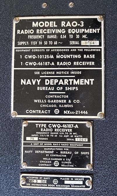
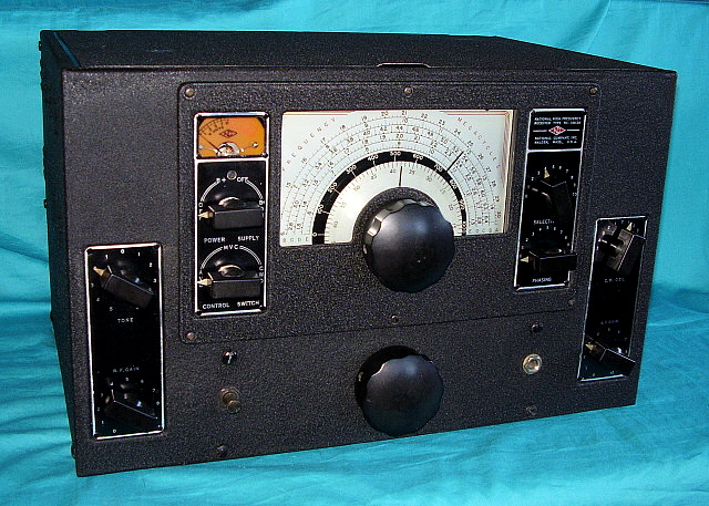
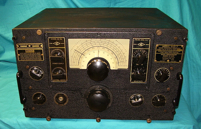
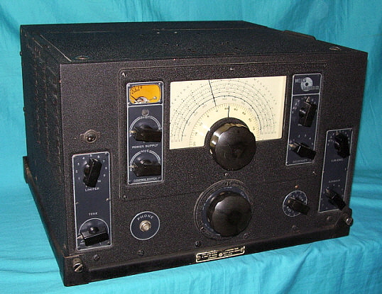
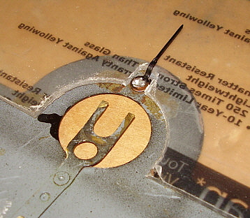
photo above: The "parts set" data plates shown now installed on
my old RAO-3 using the original hardware from the "parts set."
These original data plates are the celluloid plastic type of
data plate rather than the etched metal tags. |
|
Jan 17, 2021 - R&R the
power transformer cover. Removed the original four adapters for the
shock mount thumbscrews. Five bar knobs and the tuning knob are present on the parts set and
they are original WG knobs. Will have to soak the set screws with
penetrating oil as they are really stuck. R&R the 1st RF amplifier tube
cover. Removed the replacement audio output transformer from the old
RAO-3 and removed the original audio output transformer from the parts
set. Installed the original audio output transformer in the old RAO.
Installed a reconditioned Centralab 500K audio taper pot for the AF Gain
control and installed.
Jan 18 - Worked
with stuck set screws on the six original knobs on the parts set.
Penetrating oil and heat worked on all but one set screw that
unfortunately had the hex rounded so it was impossible to remove with
the proper tools. A reverse flute drill bit might be able to break the
set screw loose to save this original bar knob. The 2006 restoration replaced all but two WG bar knobs with
National bar knobs. Fortunately, the tuning knob and the band change
knob are original WG knobs. At any rate, if I can salvage all the WG
knobs on the parts set, I'll only be short one WG bar knob with all
other knobs on the receiver being the correct WG types.
Jan 19 - Removed the
three oil-filled filter capacitors from the parts set. All three tested
at 4.6uf with cap checker. Removed the two
dial lamp harnesses from the parts set.
Jan 20
- The set screw from the last bar knob wasn't going to come out so I
used a Dremel tool with cut-off disk to cut the shaft of the NL control.
With the knob removed now the brass shaft can be drilled out easily and
the knob salvaged. With the last knob removed the entire front part of
the cabinet was dismounted. This allowed easy access to the chassis
components I needed to dismount. Removed Crystal Filter assembly.
Removed BFO coil-capacitor assembly. Removed 2nd and 3rd IF
transformers.
Jan 21- I removed the
side cover on the soon-to-be transplanted Crystal Filter for a close
inspection and to clean the Selectivity switch with De-Oxit. No problems
were seen. Transplanted the Crystal Filter assembly into the old RAO-3.
From the wiring wraps, it looked like the old Crystal Filter had been
removed at some time in the past, hmmm. Also, the front bend was causing
a misalignment of the Selectivity switch shaft. The replacement assembly
sets "square" on the chassis and the two shafts are straight. When I was
removing the old BFO can, I noticed that the BFO tube socket was badly
broken. From the top it looked like just a hairline crack but from
underneath a large section of ceramic was missing and one tube pin
receptacle was hanging loose. I guess it has been that way all the time
I've had the receiver. At any rate, I replaced the broken socket with
the BFO tube socket from the parts set. Then transplanted the BFO can.
The bend in the old BFO can was severe and looked like it stressed the
variable condenser although it did function okay. |
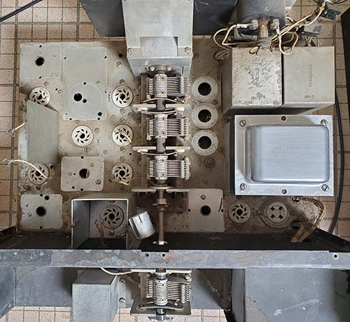
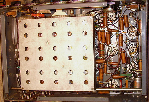
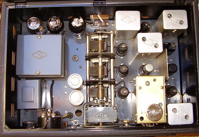
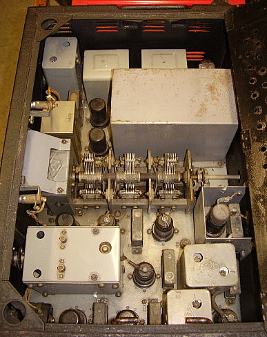
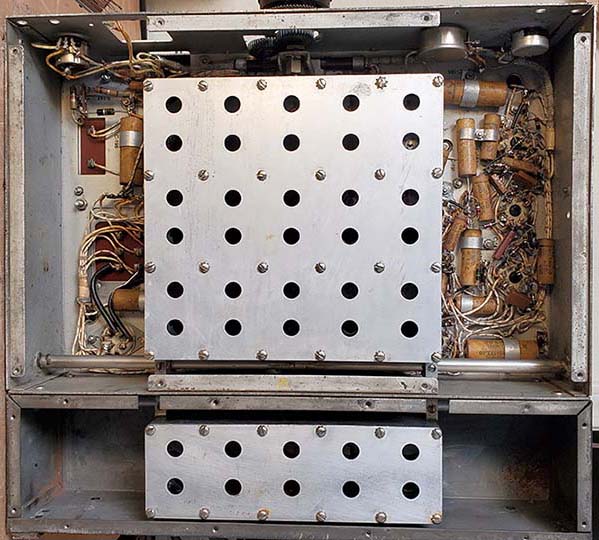
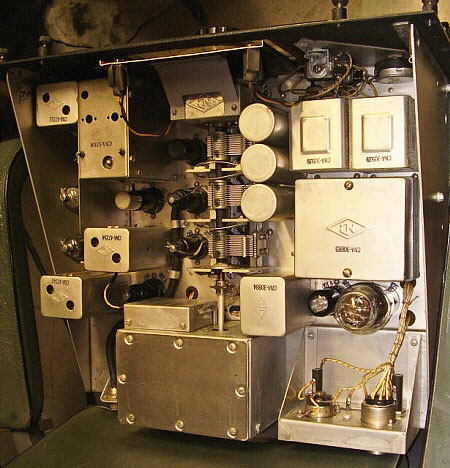
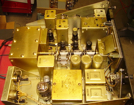
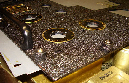
photo above: The RAO
"parts set" with most of the major parts removed for
reinstallation into the "old RAO-3." Parts that still need
extraction are the RF Amp box and the 6C8 shield. The power
transformer cover shown is the non-original from the "old RAO-3." |
|
Jan 22 - Installed 2nd IF
transformer. Removed 3rd IF transformer from old RAO-3.
IMPORTANT NOTE: When cleaning
the chassis to install the replacement 3rd IF, I noticed that under the
1st RF Amplifier tube socket there were some paper-wax capacitors
installed. These are impossible to see unless the 3rd IF transformer is
removed (maybe a dental mirror might help
to see them,...if you know they're there.) These three capacitors can't be replaced unless the entire
1st RF Amp assembly is first dismounted and removed from the receiver. There are three wires that need to be
unsoldered to remove
the entire 1st RF Amp assembly (besides the six screws that mount the
assembly to the back vertical cabinet wall.) Additionally, the 3rd IF
transformer has to be dismounted to allow the RF Amp box to be tilted
over so the plate connection can be unsoldered. Even with the 3rd IF
transformer removed the space is very restricted. If one knows about the
RF box caps and is also planning on removing the IF transformers then, with
the 2nd and 3rd IF transformers extracted, the space to remove the RF box
is much larger making the job easier. Once the RF Amp box is dismounted,
then access to the capacitors is not restricted. I had to rebuild the three
paper-wax caps in order to be able to then remount the 1st RF amp
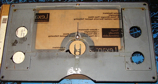
assembly and then the 3rd IF transformer could be reinstalled. Photo to
the right shows the bottom of the RF Amp box with the rebuilt original
paper-wax capacitors (new polyfilms inside) installed.
Brief
Capacitor Rebuilding Description - Restuffing caps consists of first
using a hand-held heat gun to melt the wax in order to remove the old
capacitor from the shell. The shell is wiped (while still hot) with a paper towel to
remove the excess old wax which results in a clean empty original
capacitor shell. Next a polyfilm capacitor is "sized" by wrapping it
with masking tape until it fits into the shell without falling out. Then
the ends are filled with hot-melt glue leaving about .125" to .250" gap
at the ends. The ends are then filled with melted bee's wax. When the
end cap wax has set-up, then the entire exterior of the capacitor shell
is coated with melted bee's wax. When completed, it's very difficult to
tell the rebuilt from an original. Polyfilm cap orientation shouldn't
matter but I always install the caps with the left lead as the "outside
foil" when holding the capacitor in the right hand and the value writing is
viewed as "rightside-up."
Jan 23 - Cleaned the tray
area under tuning condenser with denatured alcohol. This area always
collects all of the debris that makes it into the receiver cabinet over
the years. Lots of greasy dust type dirt that cleaned easily with the
denatured alcohol using small long handle paint brushes and long handle
Q-tips. Detailed cleaning on the tuning condenser was also
done. Cleaned the chassis ground connections and then installed the
three oil-filled paper-dielectric filter capacitors. The three
oil-filled caps were apparently removed sometime in the past (before
1969) and not reinstalled correctly. The insulating washer was next to
the capacitor body and the grounding washer was next to the chassis. The
grounding washer should be next to the cap body to connect it to chassis
ground (not an electrical connection but for shielding) then the fiber
washer is next to the chassis. Not a serious mistake but still not
correct. I'm beginning to discover that my old RAO-3 had been worked on
extensively and not by any Navy depot. While the rework is generally
okay, it wasn't at a professional level that would indicate depot rework. |
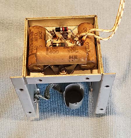
photo above: The 1st
RF Amp box showing the three rebuilt capacitors installed on the
underside of the assembly. |
Jan 24 - Started
rebuilding the paper-wax capacitors. I'm removing a small quantity of
original capacitors from
the "parts set" and then rebuilding those. Once that
quantity is finished I then remove the same value caps from the old RAO and
then install the rebuilt ones. I rebuilt the six paper-wax caps on the power
supply side of the chassis. These along with the three under the RF box
total nine caps rebuilt and installed so far. Both the "parts set" RAO
and the old RAO have a few non-original capacitors so a few of the same
value caps from the old RAO will need to be rebuilt and then reinstalled
into the positions that had non-original maker caps. The end-result will
be that all paper-wax capacitors will appear to be original CBV types
but will have modern polyfilm capacitors inside.
 |
Jan 25 - Rebuilt the two
1uf 200vdc caps, the two .05uf 400vdc caps and the three 0.1uf 600vdc
caps. Then installed them into the old RAO-3. 16 caps rebuilt so far.
Jan 26 - Rebuilt eight
.01uf 600vdc caps.
Jan 27
- Installed all of the .01uf 600vdc rebuilt caps. 24 caps
rebuilt and installed. I removed the remaining .1uf 400vdc caps
from the "parts set" with the exception of C189
that has a unique clamp mount. For C189 I used the
original from the old RAO-3. These eight caps were rebuilt and
then installed bringing the complete total of rebuilt paper-wax
caps to 32.
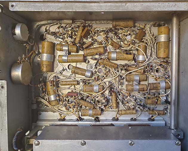
photo left: Under the IF/AF side of the chassis
showing how the rebuilt paper-wax capacitors are difficult to
tell from the original CBV paper-wax capacitors. Note that only
the .01uf paper-wax capacitors and one .05uf capacitor and one
.1uf capacitor don't have clamps to secure them
to the chassis.
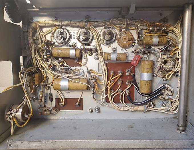
photo right: Under the power supply side of the
chassis showing the rebuilt CBV paper-wax capacitors located there.
|
 |
Jan 28 - Replaced the
three newer style dipped mica capacitors with original
style, tested vintage mica caps (this was for under-chassis
appearance only.) Some of the original mica capacitors used in both WG RAO-3
receivers seemed to have defective leads. The lead wire seems to be very
brittle and easily breaks when trying to extract the capacitor. One
of the original receiver problems back in 1969 was due to a broken lead
on a mica capacitor. It's probably why the three dipped mica caps were
installed. My thought is that if an original mica cap can be extracted
from the "parts set" without damage then the leads are probably not
defective. About 50% of the mica caps in the WG RAO-3 receivers seem to
be affected. Part of the "test" besides measuring the value was to
determine that the lead wasn't brittle.
Replaced the grid leads to the 6C8G and the 6F8G tubes. The "parts set"
wires were in better condition than those in the old RAO. I was going to
replace the S-meter lamp wiring because the two wires were "friction
taped." But, the wires are within a laced harness and removal of the
wires would probably break the laces. Instead, I replaced the friction
tape with original black spaghetti tubing which looks more convincing as
original. The wire from the S-meter switch to the meter also had
friction tape on it so I used the good condition wire from the "parts
set" as a replacement. Grid connection wire to the 2nd RF amp had friction tape so repaired with black
spaghetti tubing. Installed the NOS S-meter and installed original lugs
for the meter connections, also used original meter stud nuts and washers. Installed
the original type of S-meter lamp socket. I had a screw base #40 lamp
installed,
should have been bayonet base #47. The rubber grommets on the lamp
socket are to prevent pushing the lamp into the S-meter too far which
can overheat the meter scale and discolor it.
I added two fiber washers between the back of the logging dial hub and the
front of the gearbox hub to take up some clearance that had been
allowing the
tuning shaft to have about .090" thrust end play. Mechanically set the
logging dial to be accurate.
Functional Test -
Installed the tubes and cleaned the pins with brushed on DeOxit and then
plugged in and out a few times. Connected 600Z ohm loudspeaker, the AC
power cord and a test antenna. Power applied with variac with no
problems. Full scale S-meter indication in AVC and no signal (AVC at max
negative bias, apparently.) Loud signals in MVC, tested three bands with loud
ambient noise levels, tested Crystal Filter OK, tested BFO OK, tested
Tone OK, tested NL OK, RF and AF gain OK. Receiver is almost fully
functional with just an AVC problem. When the AVC problem is repaired,
then the receiver will be reassembled.
Jan 29 - Even
though the coupling capacitor from the detector/3rd IF transformer to
the grid input of the AVC amplifier tube (a 50pf mica) seemed to measure
okay on the cap meter, it apparently was open. Installed another vintage
50pf mica and that got the AVC functioning. Synchronized the band
indicator to the catacomb position - it has to mesh with the pinion gear
on the correct "tooth" of the drive gear in order for the correct band
indicator to be in the 12 o'clock position when that band is engaged at
the catacomb pin receiving contact blocks. Installed the combination front panel-side panels part of
the cabinet. Installed the lid, the band change bezel, the dial
escutcheon and the "back porch" cover. All original screws and lock
washers used in all of the mountings. Most of the black wrinkle finish
truss-head screws needed cleaning and touched-up. Installed the four
threaded adapters that are for mounting the receiver to the shock mount. Lightly lubed (with
grease) the two round rods that the two catacombs ride on.
Jan 31 - Operated the
RAO-3 yesterday and this morning to allow any unusual issues to turn up
but the receiver performed quite well. I was thinking about not doing an
alignment because the sensitivity was okay and the tracking was very
good. Luckily, I did do a full IF/RF alignment in the afternoon. The IF
was slightly improved with the alignment. Tracking also was very
close but Band C did need the lower end slightly touched-up to be
accurate on the 40M band. Audio is very good although it is
"communications grade" but the bass response isn't lacking, it just
isn't emphasized. The problem of the slight frequency change in the BFO
as the RF Gain is adjusted in MVC is now only encountered on Band A and
even there it's just barely noticeable compared to what it was prior to the
rebuild.
| RAO-3 Performance
- There's no doubt that after 50+ years of ownership,...it was
about time that I rebuilt this receiver correctly. As I mentioned
somewhere earlier, this RAO-3 was only a 26 year old piece of
equipment when I found it in 1969. I had always run it on its
mostly original parts that were now over 75 years old. So,...was
improvement noticeable after all of the rework was finished?
Absolutely! Here's what I've observed as definitely better
performance: 1. Audio response
- certainly replacing the "universal" audio output transformer
with a good original RAO-3 audio output transformer was the
major reason for the improved audio. A second improvement must
have also been the replacement of the incorrect "linear taper"
AF Gain pot with an "audio taper" pot that now results in a
fully adjustable audio gain. Of course, slightly leaky
capacitors can also skew bias voltages and affect low frequency
coupling, so the capacitor rebuild also added to the much
improved audio. Additionally, I had been running a beam power
pentode 6V6 as the audio output tube and the correct tube is a
pentode 6K6. NOTE: I
didn't change any values of C, the values I used are original to
the receiver design.
2. Selectivity - this
improvement is due to the replacement of the damaged
Crystal Filter assembly. The old unit had a severe "crunch" in
the front that was putting stress on the Selectivity switch and
the Phasing condenser with the misaligned wooden shaft prevented
smooth adjustment.
Accurate alignment of the replacement Crystal Filter also must
have helped. The Crystal Filter is now fully operational and a
valuable tool to combat QRM.
3. Sensitivity - when
listening to 40M SSB nets the RF Gain is now at 4 or 5 with the
AF Gain at 8. 20M SSB stations are normally between 5 and 7 for
the RF Gain. Trenton Military on 15.065mc is easy copy. TAH
(Marker Beacon, Istanbul, Turkey) copied on 8.35mc. All of the
marker beacons from Seoul, Korea were easy copy at 12.9 mc. Nice
improvement.
4. Dial Accuracy -
this was always pretty good but is even better now with the
recent RF tracking touch-ups.
The best compliment for a receiver rebuild is to actually be
able to enjoy using that receiver in a vintage military station
while it successfully and repeatedly provides reliable
communications with fine articulate audio,...just as
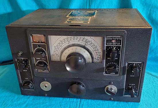
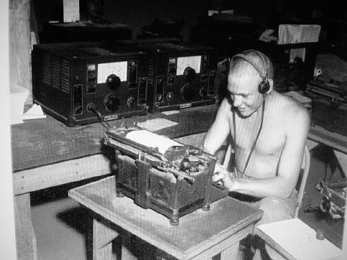
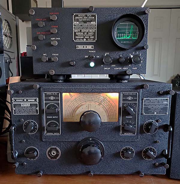
seen in the photo to the right. This setup has been in use weekly use since
early February 2021. |
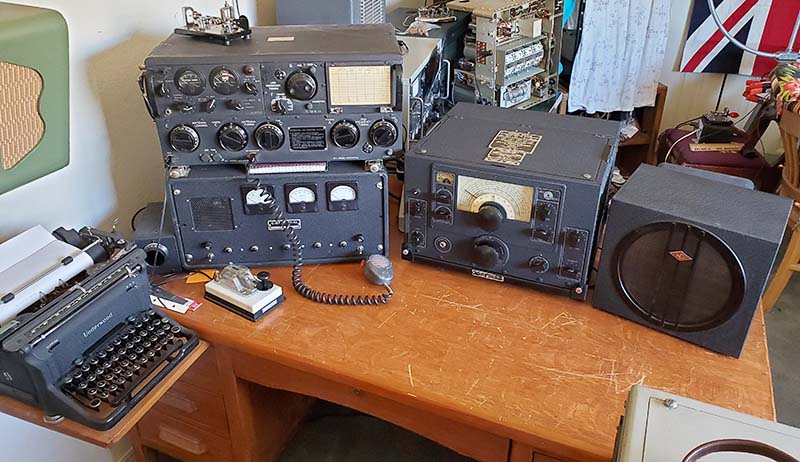
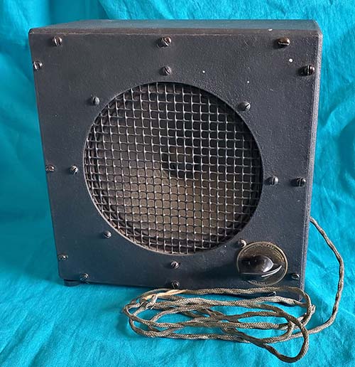
photo above: Left to
right - WWII Underwood SII "Mill" typewriter, Navy-Collins T-47/ART-13
transmitter on top of the vacuum tube power supply (homebrew,)
Navy RAO-3 receiver with a National MSC-10 speaker cabinet with 10"
PM speaker with a 600Z matching
transformer, Shure 102C carbon mike, a Hi-Mound HK-710 handkey and,
on top of the ART-13,...a Vibroplex Original "bug."
|
| UPDATES:
Dec. 16, 2021
- I'd been operating
the RAO-3 directly on the 124 volt AC line which will slightly increase the
tube filament voltage and also increase the B+ somewhat. The RAO
was designed for 115vac input and the easiest way to adjust the
AC line is to use a "bucking transformer." I looked through the
filament transformer box and found a 6.3vac 6A transformer made
by Triad. I wired it up to "buck" the voltage and the resulting
AC input to the RAO was now 116vac. I just use power cable for
wiring with an AC plug and an AC cable receptacle. All
connections to the transformer leads are soldered and insulated
then tie-wrapped to the mounting flanges for security. The
bucking transformer just sets behind the RAO and is connected to
the power strip that powers up the station. With that way of
connecting the bucking transformer, it's only powered up when the strip
is turned on and that only happens when the station is in use.
No real obvious difference in RAO operation but the filament
voltage is now 6.3vac and the B+ is around +200vdc.
Oct. 11, 2022
- I've been listening to the RAO-3 lately and I'm beginning to
wonder about the AVC. When switched in, the AVC throttles-back the RF/IF
gain to the point where it seems that the AVC bias is dependent
on the received noise rather than the signal. There doesn't seem
to be very much change in the AVC bias in relation to the signal
level. Although the S-meter appears to be working, on higher
frequencies tuning off signal and back on signal doesn't really
change the S-meter indication (responding to received noise) that might be reading S-6 or so.
Performance in CW is great with good sensitivity easily up to
20mc. In reading the original Instruction Book for the RAO-3, nowhere in the manual is the reception of "voice" or "music"
mentioned. Only CW or MCW modes are shown. AVC is an option for
measuring signal strength in CW with the BFO off or for Sensitivity control in
MCW. This implies that the RAO-3 receiver was normally
operated in the MVC position and AVC was only used briefly for
checking signal strength. This would seem to be how the RAO-3
works best with the greatest sensitivity, that is, regardless of
the mode, always in MVC, riding the RF Gain control. |
|