Radio Boulevard
Western Historic Radio Museum


Pre-WWII and Post-WWII

COMMERCIAL & MILITARY RADIO COMMUNICATIONS EQUIPMENT

  -  PART TWO  -

1949 - 1969

(USA, UK & Germany)

photo: Artwork from TDP-1 Direction Finder Manual


Pre-WWII and Post-WWII

Commercial & Military Radio Communications Equipment - 1932-1942 & 1946-1960s
Airport, Shipboard, General Purpose and Military Gear

PART TWO


Signal Corps/Hallicrafters R-274/FRR sn: 762

 Signal Corps U.S. Army/The Hallicrafters Co.  -  R-274/FRR, R-274D/FRR (aka: SX-73)

In the post-WWII era, the U.S. Army Signal Corps needed a source of high-quality, frequency-stable receiver that had specific Signal Corps design requirements. The main features were a selectable crystal oscillator to virtually eliminate frequency drift in the LO and BFO for reliable RTTY reception. A rotating turret band switch was required for ease of maintenance and eliminating the conventional, problem-prone band switch. Both Hammarlund and Hallicrafters built successful versions of these types of receivers. Although WWII Hammarlund Super-Pro receivers had been modified by the Signal Corps to have the selectable crystal oscillator in 1947 through 1949, the quantity of available receivers was limited. The Signal Corps needed a manufacturer that could deliver a new receiver with the specified options in fairly large quantities. It's fairly obvious that most of the R-274 is a Signal Corps design and that Hallicrafters was the contractor chosen to build the receivers. The first R-274 receivers were built on a 1949 contract. It's very probable that Hammarlund had also been working closely with the Signal Corps and the SP-600 was their combined effort. Hammarlund had been advertising their SP-600 since 1948 (as the SPC-600-X) but apparently the receiver wasn't available until 1950. The Signal Corps didn't want to assign a new designation to a similar receiver (since they were so closely involved with the design of both receivers) so the Hammarlund SP-600 was assigned R-274 with suffixes A, B or C used for specific identification. Future R-274 receivers contracted to Hallicrafters would be designated as R-274D.

The typical post-WWII military contract production quantity was probably relatively small, perhaps 1000 receivers per contract. It doesn't seem likely that Hallicrafters would have gone through the effort for one contract. Hallicrafters probably thought there would be many more contracts in the future but that doesn't seem to be the case. The Signal Corps obviously favored the Hammarlund version and literally tens of thousands of SP-600s were supplied to the Signal Corps over the next decade. Since Hallicrafters had invested in some production line tooling and had obviously set up component suppliers for production, they decided there might also be a commercial or even a ham market for their receiver. The civilian designation assigned was SX-73 and these receivers are virtually identical to the R-274D except for the ID tag, which shows "SX-73" as the receiver type. Some advertising mentions that a cabinet was supplied with the SX-73 though advertising artwork generally shows the receiver in the rack mount configuration. Selling price was quite high at $975 which certainly limited purchases of the SX-73 by the civilian market. The SX-73 version is seldom seen and production must have be very limited. The R-274D and SX-73 were available from 1952 up to around early-1954.

The R-274/SX73 is generally referred to as "Hallicrafters' version of the SP-600" or the "Hallicrafters' Super-Pro" since there are so many similarities between the two receivers. The similarities are to be expected since both receivers were "designed" with major influence of the Signal Corps and both receivers had to meet Signal Corps' design specifications. The most obvious similarity is the turret band switch which, while functionally the same at the SP-600's, is not nearly so robust in construction using heavy-duty plastic module bases with stub pins pressing against flex contacts. The SP-600 coils are on a ceramic base with longer pins passing thru dual pinch contacts. The tuning dial provides a main dial and a logging dial as the SP-600 does but behind a single escutcheon rather than separate dials behind two escutcheons as the SP-600 does. There is a selectable six-channel Crystal Oscillator that functions like the SP-600 "X" option and provides improved stability for RTTY and other data modes. Like the SP-600, the bandwidth is selectable in six selectivity steps with three of those steps using a Crystal Filter for narrow bandwidth (a front panel Phasing control is also provided.) A 600 ohm balanced audio output is also similar to the SP-600 audio output.

One major difference between the R-274/SX73 and the SP-600 circuit is the conversion frequency of the SP-600 is 3.955mc while the R-274/SX73 uses 6.455mc. Also, the placement of the conversion frequency with reference to tuning range four has the double conversion starting at 7.0mc on the R-274/SX73 while it is 7.4mc on the SP-600. This results in double conversion being used for the 40 meter ham band on the R-274/SX73 but not on the SP-600.

The R-274/SX73 frequency coverage of each tuning range is beneficial to the ham user in that 160, 80, 40 and 20 meters are on separate tuning ranges while the SP-600 combines 80 meters at the low end and 40 meters at the high end on tuning range three. In the audio section of the R-274/SX73, the coupling capacitors are .01uf in the R-274/SX73 while the SP-600 uses .0015uf capacitors. This results in the "communications-grade audio" found in the SP-600 while the R-274/SX73 has a more conventional audio response. Additionally, the R-274/SX73 provides an Antenna Trim control while the SP-600 does not. Possibly the most important difference between the R-274/SX73 and the SP-600 is that the former receiver utilizes almost entirely ceramic disk capacitors in the circuit rather than the "leakage-prone" molded capacitors that have negatively influenced the reliability and reputation of all early SP-600 receivers. In considering the restoration of the R-274/SX73, the ceramic capacitors will certainly and positively reduce the amount of rework that is going to be necessary.

Some of the components used in the R-274/SX73 are of a better quality than those found in the SP-600 - IF transformers and the bulk of the capacitors used, for example. But some other parts and components are not as high of quality as those found in the Hammarlund - band switch turret, the dial gear train and the dial lock, for instance. The R-274/SX73 tuning condenser bearings are of a very poor quality and can rust excessively in a humid environment which can cause "sticking" and "jamming" of the tuning condenser's rotation. The R-274/SX73 tuning dial itself along with the logging dial are difficult to read (some users find the same fault with the SP-600) and the R-274/SX73 dial illumination is subtle (dim really) while the SP-600 dial illumination is dazzling. The Carrier Level meter has only a Decibel scale that references 0db as mid-scale on the meter which is equal to 50uv input signal level. Performance is the final judgment though and the R-274/SX73 will easily provide the user the same high sensitivity and quality reception as the SP-600 along with much better sounding audio reproduction.

It's obvious to R-274 owners who have taken the time to carefully examine their receivers that Hallicrafters' engineers did not design the R-274. It's a product of Signal Corps engineering with Hallicrafters manufacturing the R-274 to Signal Corps specifications.


photo above: The R-274 mounted in its military table-top cabinet, the CY-699/FRR


1953 Hammarlund SP-600-25C

Hammarlund Manufacturing Co., Inc.  -  SP-600 Series

Officially introduced in 1950 and with production starting in late-1951, the SP-600 was intended for the military and commercial user market. It was a very popular receiver even though the selling price was nearly $1000, but many thousands were built, especially for military applications. It's known that much of the SP-600 design input came from the U.S. Army Signal Corps, especially the selectable crystal oscillator and the turret band switching sections. The Signal Corps did have some WWII-version Super-Pro receivers modified with three-channel crystal oscillators in 1947-49 (R-270/FRR receivers, also other Super-Pro receivers with Improvement Kit MC-531 installed - see R-270/FRR section above.) The Signal Corps must have been working with other companies to find acceptable receiver manufacturers for their requirements because, in 1949, the Signal Corps contracted with Hallicrafters to build a Super-Pro "type of receiver" that met their design requirements. The Hallicrafters receiver was designated R-274/FRR with its first contract being issued in 1949. The SP-600 was first ordered in a 1950 contract that was for a R-483 receiver (JX-5.) The first R-274A Hammarlund version was on a 1951 contract (JX-1) and this was the first SP-600 officially produced in November 1951. Hammarlund used R-274A and C designations for Signal Corps receivers and R-274B for USN receivers. Hallicrafters versions was assigned the suffix D on the next contract (1952.) Eventually, the Hammarlund SP-600 was the choice of the military who ordered tens of thousands of them over the next decade while Hallicrafters' version was not ordered after only two contracts (1949 and 1952.) It's estimated that ultimately a total of around 150,000 SP-600 receivers were produced from 1951 up until 1972.

Though most Hammarlund SP-600 versions were built throughout the 1950s, the SP-600 continued to be produced in smaller numbers up into the early 1970s. The standard SP-600 tunes from .54 to 54MC in six bands. A "J" suffix indicates JAN parts were used in the construction and an "X" suffix indicates a selectable crystal oscillator for maximum stability as the LO. Hammarlund also offered a "JL" version with 100-400KC substituted for the .54-1.35MC band and a "VLF" version that covered 10-540KC (details on the SP-600VLF version in photo caption below.) Hammarlund made over 40 variations that were assigned a numerical suffix which identified the particular circuit, mechanical changes or sometimes the end-user. The last in the "time-line" was the model variation SP-600 JX-21A from 1969-1972 which utilized a product detector circuit, two additional tubes, different knobs and some other changes to make it "compatible" with SSB operations.

Most versions use a 20 tube double conversion superheterodyne circuit with a rotating turret bandswitch. The receivers also feature enormous proportions, robust construction and oversize controls - along with a super-smooth tuning system that only adds to the enjoyment of operating these fine receivers. Double conversion is switched in above 7.4MC and uses a crystal controlled conversion oscillator. Though the SP-600 has two dials, it has no bandspread - the right side dial is a logging scale allowing precise retuning of desired stations. On the left is the main tuning dial and the mechanically articulated dial pointer that indicates which tuning scale is in use (along with the small window between the dials that shows which tuning range is selected.) The tuning arrangement was an up-dated version of the "Continuous Bandspread" system introduced in RCA's AR-88 series receivers in the 1940s. The frequency readout accuracy is vague which is why a precise logging scale system is incorporated into the SP-600 design. The meter is not illuminated and a switch is provided to indicate either carrier level or audio output. Most (but not all) SP-600 model numbers usually will have a suffix with "J" or "JX" followed by a numeral. As mentioned above, suffix "J" indicated that, as much as possible, military level components and construction were used. Suffix "X" indicated that a selectable six-position, fixed-frequency crystal-controlled oscillator was installed that allowed the user to install HC-6/U type crystals for specific desired LO frequencies. The VFO position allowed the receiver to operate with the standard LO while the positions 1 to 6 turned off the LO and turned on the Crystal Oscillator while allowing selection of any of the six crystal-controlled frequencies. Although the user could switch to any of the crystal LO frequencies for increased stability for that particular frequency, the receiver still has to be "tuned" to the desired frequency for the RF and Mixer stages to be in tune.

Many SP-600 receivers were set-up for diversity operation and the standard diversity model was the JX-17 version. This version was produced in large numbers and can be easily spotted by observing that it has two extra controls and uses three red colored knobs. The SP-600 Audio output is about 2 watts from a single 6V6 using a balanced split-winding audio output transformer for 600 ohms Z. The audio quality from a rebuilt SP-600 is communications-grade audio with the lower end rolled off at 125Hz 3db down. This audio shaping, while noticeably lacking bass response, was designed into the SP-600 to allow excellent copy in all modes whether it be CW, RTTY (or other data modes) along with greater intelligibility of weak signals in voice modes (either AM or SSB.)

The number following the letter suffix generally indicates specific features for that version, e.g., contract or end user, circuit upgrades, etc., with the number ranges being more or less chronological until the last of production. Though the number suffixes were more or less chronologically assigned, many of the versions were built over a fairly long time period. This meant that engineering and component changes were being added as receiver production continued. The end result today is that there are early and later versions of many of the numbered suffix models and documentation is not always specifically accurate based just on the number suffix. It is more accurate to use the build date of the receiver and use documentation that is dated close to the receiver manufacture date.

SP-600VLF-31  -  Shown in the photo to the left is the SP-600VLF-31 receiver from 1958. This version covers 540kc down to 10kc in six tuning ranges and uses 21 tubes. The SP-600VLF is NOT a standard SP-600 with LF coils installed in the turret. The VLF version  uses very different circuitry but with the mechanics and general construction being similar to standard Hammarlund SP-600. The circuit of the SP-600VLF uses a 705kc IF and is a single conversion receiver. Double pre-selection is employed on all bands (two TRF amplifiers.) The "X" option crystal oscillator provides four channels (instead of the six like the HF version) and uses FT-243 type crystals. Five selectivity positions are provided (instead of six like the HF version.) The dual Crystal Filters are always in the circuit regardless of the selectivity position used. The 455kc IF output is accomplished by mixing the 705kc IF with a 1160kc crystal oscillator (this circuit requires two tubes, 6C4 oscillator and 6BE6 mixer.) The 455kc IF was for driving data devices such as RTTY converters. The chassis and the side panels are iridite finish and the side panels are similar to those used on the R-390A receiver. Since the VLF receivers are from the late-fifties, ceramic disk capacitors are used throughout the circuit. 

The SP-600VLF provides tremendous sensitivity and due to the high levels of noise in the spectrum below 500kc usually a tuned loop antenna will be required for the receiver to operate at its full potential on MW. Generally, a remotely-tuned loop antenna or a shielded magnetic loop antenna will greatly reduce the RFI noise levels and it can also provide directivity that may also help in reducing interference from some types of local noise. Below 100kc, an outdoor, large wire antenna will be necessary since most loops won't tune below about 150kc. Nearly all signals in the LF spectrum are now digital data signals or various types of beacons with virtually no voice signals at all. The times that the receiver would be set up with AVC and MOD selected would be few and most listening will be in CW-MAN turning on the BFO and operating the RF gain manually.

Best Performance using the SP-600VLF will require a "RF-quite" location, a tuned loop antenna or a shielded magnetic loop, either of reasonable size (minimum 3' diameter) and monitoring with a 600Z headset on the audio output since many DX signals are "in the noise" and barely detectable. For MW, LF and VLF listening or for 630M operations using a vintage vacuum tube receiver, the SP-600VLF is one of the best performing "Long Wave" receivers and maintenance is infrequent but easy to accomplish if necessary.

The Tubular Capacitor Problem - All early versions (1951 to about 1954) of the SP-600 receivers were built using molded tubular paper dielectric capacitors of various manufacture - Cornell-Dubilier (most common) and Sprague (sometimes) are the types encountered. Nearly all molded capacitors are defective nowadays, requiring extensive replacement work when rebuilding an SP-600. In fact, it's quite common to find a few burned resistors in an un-rebuilt SP-600 due to leaky or shorted molded tubular capacitors. Later versions (mid-fifties on) had much more reliable ceramic-disk type capacitors installed rather than the problem-prone molded capacitors. All early SP-600s will require a rebuild for the receiver to operate at the high level of performance that it is capable of. Molded capacitor replacement requires some major disassembly of the various units in the receiver. The turret bandswitching assembly has 6 capacitors inside, the RF platform has 20 capacitors inside, the IF transformers have 1 or 2 capacitors inside, T1 has 1 capacitor inside and the conversion crystal oscillator has 3 capacitors inside - all these units have to be partially disassembled to access these molded capacitors that need to be replaced. The JX versions will have the switchable crystal oscillator that also needs rebuilding (2 molded caps inside.) Additionally, there are many other molded capacitors under the chassis. Most SP-600s will have over 50 capacitors that will need replacement - a challenging task but absolutely necessary and well worth the effort required. After a rebuild, the SP-600 will need a full IF-RF alignment for a performance level that meets or exceeds original specifications. The decision of whether or not to rebuild an early SP-600 is not really an option - all early SP-600 receivers need to be rebuilt for safe and proper operation.

For more details on rebuilding the Hammarlund SP-600 receiver, read our article - "Rebuilding the Hammarlund SP-600" - use Home/Index for navigation

photo right: 1953 Hammarlund SP-600 JX-21


Collins Radio Co. - Military and Commercial Equipment


1950 Collins 51J-2 in original style cabinet. Note the green highlighting of the 40 meter amateur band

Collins Radio Co. - 51J Series
(includes 51J-1, 51J-2, 51J-3, R-388/URR and 51J-4)

Collins was developing a precision general coverage receiver starting late in WWII. It's likely that the 51J-1 receiver was available around 1947, concurrently with the ham band 75A-1 receiver. The market for an expensive general coverage receiver was limited at the time so production levels were very low. Collins sent a couple of 51J-1 receivers to the Signal Corps and to the Navy to "try out." The 51J-1 was ideally suited for RTTY and could be essentially used without any modifications by just adding the RTTY accessories. The military was impressed and started ordering 51J-1 receivers that were then designated as the R-381 receiver. The first real advertising for the 51J-1 started in late-1949, with the emphasis on the 51J-1 for the commercial user or for the individual/enthusiast providing accurate frequency readout and great stability. The initial 51J receiver utilized a permeability tuned circuit using the 70E-7A PTO along with a dual tunable IF system and a multiple frequency Crystal Oscillator to cover .5mc to 30.5mc in thirty (1mc wide) bands. The dual tuned IF is switched between odd and even bands (referencing the center frequency of each band, thus the 6.5mc to 7.5mc range would be Band 7, an Odd Band.) Three fixed frequency (500kc) IF amplifiers are used. Adjustable selectivity is provided by a Crystal Filter. A standard envelope detector and Noise Limiter are also in the circuit. Band 1 actually is triple conversion but only to allow coverage of the AM BC band. Bands 2 and 3 are single conversion (since they are the output of the dual tunable IF) while all of the remaining bands are double conversion (working with the 10 frequency Crystal Oscillator.) 16 tubes are used in the 51J-1 and J-2. On the early versions, the ham bands are high-lighted in green on the megacycle drum dial but, at nearly $900, not many hams could afford a 51J as their station receiver. Early versions also have a metal dial bezel, the Collins' "winged emblem," no grab handles and an illuminated S-meter. Audio response is restricted at 200 to 2500Hz and is definitely not high fidelity, usually sounding somewhat "muffled" when receiving AM voice signals. The very narrow IF passband of 4kc at -6db was also responsible for the restricted audio highs. The most apparent difference between the 51J-1 and 51J-2 is that the latter added an Audio Output function to the S-meter which became a Carrier Level/Audio Output meter that was actuated by a toggle switch next to the meter. The 100kc Crystal Calibrator nomenclature was "100 KC OSCILLATOR" on only the first few 51J-1 receivers and was quickly changed to "CALIBRATE" on the majority of 51J-1 receivers and all 51J-2 receivers. The 51J-1 was produced in very small quantities from 1947-49 while the 51J-2 was somewhat higher in production quantity being produced from late 1949 thru most of 1950. 51J-1 receivers were supplied to the military as the R-381/URR and 51J-2 receivers went to the military were identified as the R-381A/URR receiver.


1952 R-388 installed in a CY-1260/G Receiver Case

In 1950, the updated and improved military version 51J receiver, the R-388/URR, was introduced, featuring an 18 tube circuit (adding a voltage regulator and vfo buffer,) a new version of the PTO (70E-15) and eliminating the fixed 300 ohm Z antenna input (by removing the primary winding on the antenna coils) and redesigning the antenna input to a more flexible design with an Antenna Trim control. This revision was probably at the request of the Signal Corps, who found the R-381 (51J-1) or the R-381A (51J-2) difficult to use for some of their teletype installations because of the fixed 300 ohm Z antenna input requirement  (most of the SC installations used either 75 Z ohm dipoles or Lo-Z vertical whip antennas.) Production of R-388/URR receiver was rather high with estimates that well over 12,000 receivers were produced. The contracts started in 1950 but production levels were very small in 1950. The greatest quantity of receivers were produced in 1951, 1952 and 1953. There were additional contracts in 1954, 1955, 1956, 1957 and 1962 but the production levels in these later contracts total less than 1000 receivers. With the R-388, grab handles were added to the front panel along with a high quality Burlington Co. sealed meter although some receivers may be found with a Marion Electric meters or DeJur or even Simpson (and possibly other makes.) Additionally, the 51J-3/R-388 added an internal relay to isolate the antenna and remove plate voltage from the IF section as a Remote Break-in function. This addition required the user to provide approximately 12vdc at 135mA to operate the internal relay from the auxiliary contacts on a T-R relay.

Hallicrafters was contracted to build at least two different types of military cases for the R-388 receivers. These cases were made out of heavy gauge steel and featured glides that allowed rollers to be mounted to the R-388 chassis to ease installation and removal of the receiver from the cabinet. A dual receiver cabinet was also produced. The CY-1206/G is shown to the left with 1952 R-388 sn:161 receiver installed.

A standard PHONE jack provided 4 Z ohm output and a PL-68 type jack provided a 600 Z ohm SPEAKER output both mounted on the front panel on the early versions. 1953 and later versions had a "Break-in" switch that replaced the front panel SPEAKER jack. Some early receivers were later reworked by the military to replace the front panel speaker jack with the "Break-in" switch. The rework was performed per a MWO (Military Work Order) and sometimes the particular MWOs will be listed on the receiver panel as shown in the photo to the right.

Nearly all R-388 aluminum top covers will have the receiver schematic on the underside of the cover. Very late R-388s will have the pin jacks on the rear chassis apron for AVC and Diode Load (same as the 51J-4.) 

The serial number that is punch-stamped on the rear of the chassis apron is a Collins' production assigned number that usually was sequential for most of the production (for approximately the first 10,000 receivers) however the ID tag's serial number was sequentially assigned for the specific contract only. These two serial numbers never match and considering how they were assigned, shouldn't.

Almost all R-388 receivers had a 70E-15 "M" PTO installed. The "M" was a prefix added to the serial number and identifies the PTO as for the R-388. The type of ferrite used for the cores on the 70E-15 PTO had permeability stability issues when combined with 24/7 operation that caused long-term heat build-up. It took at least a decade for the ferrite problem to become recognized and by that time the contracts for the R-388 were at an end and the 51J-4 production was nearly its end also. Almost all 51J-4 receivers have "CR" PTOs installed which aren't really any different, it's the end-use of the receiver that has resulted in most 51J-4 receivers still capable of PTO End Point Error correction. There is a "fix" for the "M" PTOs that involves modifying L002 inside the PTO to move the "range of adjustability" to a frequency that does allow correction of the EPE but the actual span of the adjustability is slightly reduced.


1953 contract R-388/URR with Break-in Switch

The civilian version of the R-388/URR was the 51J-3 which was produced in very limited numbers since the major demand for the receiver was from the military and that demand was satisfied with the R-388. The civilian 51J-3 is seldom seen. These receivers shouldn't have the MFP coating applied since they were going to be in commercial or amateur use. The Collins serial number tag will identify the receiver as "51J-3" and the serial number assigned should be numerically very low. The USN version of the R-388 was identified as the URR-23-A but the USN data plate identifies the receiver as "R-388/URR." Unfortunately, many Collins documents will refer to these receivers as R-388/51J-3 since all of the items that differentiate the 51J-3 from the R-388 were added after the receiver was built, put into Collins stock and subsequently pulled from stock to fill particular orders, either military R-388s or civilian 51J-3. However, 51J enthusiasts consider the end-product, that is, that the receiver is either a R-388 with military usage or it's a 51J-3 with civilian usage.

Be aware that many so-called 51J-3 receivers are actually R-388 receivers with their ID tags removed. Also, be aware that if the 51J-3 data plate has a serial number in the 12000 range, it is a reproduction data plate and the receiver is likely not an authentic 51J-3. If there's no ID tag or a bogus serial number, check the receiver to see if there are any Signal Corps acceptance stamps to verify the model. A 51J-3 receiver shouldn't have Signal Corps inspection stamps or a MFP coating. It doesn't help identification that the Collins 51J-3 manual pictures the 51J-3 on the front cover without any data plate installed implying that was how the 51J-3 was sold.

The 51J-3 was introduced in 1950 and produced in very limited numbers up to around the introduction of the 51J-4 in 1954.

In 1954, the 51J-4, with 19 tubes and three selectable mechanical filters became available. The 51J-4 added a fourth stage of IF amplification to compensate for the insertion loss of the mechanical filters. The mechanical filter assembly utilized two 6BA6 tubes as input and output amplifiers which, while providing a total of four IF amplifiers, actually only three IF stages are tuned. The bandwidth filters used on the 51J-4 were 1.4kc, 3.1kc and 6.0kc. The filters are quite different physically from the other Collins contemporary receivers in that the 51J-4's are rectangular units that are for 500kc IF rather than the round cylindrical types found in the 75A-4 or R-390A receivers that are for 455kc IF (the R-648/ARR-41 uses the same rectangular 51J-4 mechanical filters for its 500kc fixed-IF.) The 51J-4 also added an adjustment to the overall gain of the IF amplifier section in the form of a chassis mounted potentiometer (the IF Gain pot isn't on early 51J-4 production.) The 51J-4 sold for well-over $1000 and despite its expense was still a popular receiver that could be found in coastal stations such as KPH and KMI, in overseas embassies, in commercial laboratories like Beckman, universities like Stanford and even wealthy SWLs and enthusiast-ham set-ups. Some 51J-4 receivers can be found with light gray panels. Many of these light-gray panel receivers were used "in-house" in Collins test and laboratory areas (Beckman made their own panels for their Model 7700 51J-4 receiver.) Ultimately, the 51J-4 serial numbers exceeded 7000 and some of these very late production 51J-4 receivers will have Collins S-line knobs installed. Federal Procurement catalogs specify an R-388A and R-388B - the R-388 with the mechanical filter assembly installed. It likely that these receivers were probably actually identified on their tags as "51J-4" which would account for the lack of any examples of the R-388A or R-388B. 51J-4 receivers are usually not MFP coated although there's some evidence that the first few J-4 receivers were MFP'd for some reason.

The 51J-4 was the ultimate evolution of the design that was for communications, providing top selectivity, dial accuracy and drift-free reception. But, the J-4 is notorious for poor audio quality while listening to AM SW-BC stations because of the 6kc mechanical filter provided for AM listening. The earlier 51J-1, J-2s and R-388s have their own appeal and can provide top-notch reception with decent, though restricted audio quality. Though thousands of R-388 and 51J-4 receivers were produced, very few 51J-1 or 51J-2 receivers ever turn up and when they do, they will always be severely modified. As mentioned, the 51J-3 was a very low production receiver and is seldom seen (and it isn't a R-388 receiver with the data plate removed!) Fortunately for those who enjoy using these receivers, the most common version, the R-388, is the best performer providing decent quality audio, good selectivity and competitive sensitivity with 1kc dial accuracy (if the 70E-15 PTO is functioning correctly.)


1957 Collins 51J-4 sn 2392 in original style cabinet (now owned by KB6SCO.)

For the ultimate in detailed, comprehensive information on the entire 51J Series including history, variations, circuit design, 70E-15 PTO fix, rebuilding and restoration with lots and lots of photographs, go to our three-part web-article "Collins 51J Series Receivers." Go to the Home/Index below for the navigation links.


Collins Radio Company 

R-390/URR & R-390A/URR

R-390 built from 1951-1953   ~   R-390A built from 1954-1968

Various Contractors including Collins, Motorola, Stewart-Warner, Capehart,
Teledyne-Imperial-Amelco, Electronic Assistance Corp.


The ultimate vacuum tube shortwave receiver? Opinions are diverse but most owner/users rely on their R-390A for its ability to provide solid copy in the most difficult reception conditions. Mechanical filters provide excellent selectivity. Four stages of IF amplification along with double and triple conversion schemes in the front end can provide the experienced user with the ability to "dig out" weak signals while eliminating QRM. If you absolutely must know where in the electromagnetic spectrum you are tuned, the R-390A's mechanical-digital readout can be accurate to better than 500hz. Detractors mainly focus on the mechanical complexity, difficulty of troubleshooting, cumbersome tuning, the ultra-military appearance, hefty weight and the expense of excellent examples that function correctly.


1955 Collins R-390A. Who knows what the "37.4" stencil means? (I don't.)


1951 Collins R-390/URR in a CY-979/URR cabinet

R-390 - Arguably, the R-390/URR and its later kin, the R-390A/URR, are the ultimate tube-type receivers. The first version of this incredible receiver was the R-390 featuring 33 tubes (includes the 3TF7 ballast tube,) double or triple conversion, two RF stages, six IF stages, modular construction, three audio filter settings, six selectivity bandwidths and frequency coverage from 500 kc. to 32.0 mc. in 32 - one megacycle wide - bands. It is a high performance receiver that really "shows its stuff" when conditions are poor but will also provide fairly nice audio quality when receiving conditions allow for it. The most common complaint is the cumbersome tuning that, while "parked" on one frequency is not apparent, shows up when spanning an entire band or changing ranges. Most of the "stiff tuning" complaints can be traced to an over accumulation of grease and dirt in the gear train. When clean and properly (lightly oiled) lubed, the tuning is very light and easy to manipulate. Only Collins or Motorola built the R-390 contracts which ran from 1951 through 1953. The military complained that the R-390 was very difficult to maintain and too expensive. Some of the maintenance issues involve the R-390's elaborate electronically regulated B+ circuit that uses two 6082 tubes along with two 5651 voltage reference tubes and a 6BH6 DC Voltage Amplifier tube to provide a stable +180vdc for the B+. This circuit runs quite hot and accounts for many of the problems that develop in the audio module (where the regulator circuit is located.) Since most of these receivers were operated continuously by the military, heat related issues were common (and operating the crystal and PTO ovens only added to the heat build-up.) Additionally, the R-390's gear train has a moveable "locking gear" that must be installed prior to removing the RF module (if you want to keep everything synchronized.) This gear was painted green and usually mounted with a screw on the front of the gear box. Each time the RF Module is removed and then replaced on an R-390, the KC and MC drive shaft split gears have to be reset for backlash, the Crystal Oscillator module's bandswitch has to be synchronized and the oldham coupler installed. Removal of any of the crystals in the Crystal Oscillator module requires removal of the hard-wired crystal oven. When the military complained about complex maintenance issues, they weren't exaggerating.

R-390A - Collins designed a replacement receiver that was introduced in 1954 with the designation of R-390A/URR. Though the new receiver looked very similar externally to the R-390, inside numerous changes were made to improve cost-to-performance and ease of maintenance. The new receiver's gear box was removable as a unit and synchronization would be maintained, the crystal oven just plugged into the Crystal Oscillator module (it is secured by screws though,) the B+ voltage regulator circuit became a standard 0A2 tube, the crystal calibrator was combined into the RF module (eliminating the separate Crystal Calibrator module of the R-390) and the Crystal Oscillator module was mounted to the RF module so removal of the entire RF deck kept everything synchronized together except the PTO. Most of the maintenance "quirks" of the R-390 were corrected in the R-390A. The major performance change involved the installation of four mechanical filters in the IF section of the receiver. The steep slopes of the mechanical filters gave the R-390A excellent selectivity on 16KC, 8KC (really about 11KC,) 4KC and 2KC bandwidths. The 1KC and .1KC bandwidths are crystal filter derived from the 2KC wide setting. The R-390A uses 26 tubes (including the 3TF7 ballast tube) with one RF stage, four IF stages, mechanical filters on four of the six selectivity positions, plus an 800Hz audio filter. When properly set-up, one can dig right through the QRM while maintaining excellent sensitivity making the R-390A one of the finest tube-type receivers ever built. While other receivers might have better sensitivity specifications, that's not all that's required for great performance as a communications or surveillance receiver. When all of the control functions are taken into account and the operator was familiar with the R-390A's capabilities, it was an unbeatable receiver. The R-390A was produced in yearly contracts from 1954 up through 1967 (and very small contracts in 1968 and in 1984) with many different contractors building the receivers during those years. Though the R-390A's six modules and redesigned maintenance approach made field repairs easier, it was still a complex receiver. Though the military wanted a less expensive receiver, it certainly wasn't that either.


photo right: 1967 Electronic Assistance Corp. contract R-390A equipped with a Frequency Security Cover.


1956 Motorola R-390A modified by ASA with Microdial BFO adjuster

Many R-390 and R-390A receivers were used in the crypto-surveillance world of monitoring, DFing and intercepting enemy or Cold War adversary communications and traffic from all corners of the globe. Special equipment allowed recording for decryption, decoding or translations and later special modifications to the R-390A allowed its use in Tropicom, a sophisticated spread-frequency military "jam-proof" communications system. Some R-390A receivers were equipped with a flip-down Frequency Security Cover that hid the receiver's tuned frequency from unauthorized viewing. Many of the security agencies that used the R-390A were military groups that were part of the NSA. More info below in "Microdial BFO."

The R-390 and R-390A receivers have provided reliable reception under adverse conditions for years and even though the designs are over 50 years old, they are still one of the best tube-type receivers around. R-390A receivers are still being used today, sometimes in professional applications, but also for serious SWLing and, of course, in vintage military radio ham stations around the world. Many mil-rad AM operators prefer the R-390 version for its better over-all sound quality when listening to SWBC or AM stations in general, however one must consider the maintenance challenges when selecting the R-390 for a station receiver. Another note is nowadays, many R-390 and R-390A receivers are being used in "as purchased" condition - that is, the receiver has not been rebuilt, restored or even thoroughly serviced and properly aligned (or is it "alined?") The performance of a fully functional, rebuilt (restored) and recently aligned R-390/390A is impressive. 

Contemplating rebuilding an R-390A? Go to our web-article "Rebuilding the R-390A Receivers" for easy to follow information and lots of photographs. Link below in the Navigation Index.
 

photo left: Motorola 1956 contract R-390A that was modified by the U.S. Army Security Agency (part of the NSA.) The turns counter on the BFO (called the Microdial) was to allow +/- 13kc adjustability of the BFO for demodulating Dual FSK RTTY signals.

End-User Front Panel Repaints

From time to time, R-390A receivers will show up with the front panel sporting a non-standard paint color. The original specification only calls for the panel to be painted gray. Consequently, many shades of gray are found from the many different contractors that built R-390As over the years. Sometimes though, completely non-standard colors are found and these are always "end-user" applied paint jobs. The most commonly known "end-user" paint job is the USAF/NSA black anodized panels used a Clark Air Base (see photo below.) Also seen fairly often is very light gray with black nomenclature. It's also been reported that some R-390As were refinished in Admiralty Grey, the light greenish-gray color used by RACAL for their RA-17 receivers (the RACAL RA-17C-12 was also known as R-501/URR in the USA.)

Olive Drab USMC Panels - Several years ago, a 1961 Capehart contract R-390A with an olive drab painted front was found in the Northern Nevada area. It had been supposedly repainted by the USMC. Shown to the right is another 1961 Capehart with the OD painted front panel, also found here in Northern Nevada, in 2009*. Also at one time, North Korea made the captured U.S.S. Pueblo into a museum. The ship had many R-390 and R-390A receivers onboard (well, it was a NSA surveillance ship.) There were a few color photos on the Internet that showed some of the receivers from the U.S.S Pueblo. I believe that the photos were from a visitor to the ship museum who posted them on a website. However, that posting and the photos have long since disappeared off the web. In the photos, two of the R-390A receivers appeared to have OD panels. All R-390A receivers left the contractor's facility with gray panels - it was the specification - but the "end-users" were liable to repaint during a rebuild so anything might be possible - just not original.


* Is this Capehart R-390A with OD front panel the work of the USMC? Not exactly, I built up this recreation in 2010.

Microdial BFO


Some R-390A receivers will be found with a Servo Model 1309-type Microdial installed on the BFO shaft. Some installations will have a turns-lock that limits the number of turns of the BFO shaft to protect the BFO PTO. The Microdial was installed for a specific purpose that provided ease of adjustment of the R-390A when used with special RTTY demodulators that allowed copy of not only standard FSK signals but also Dual FSK signals. The Microdial had a 10:1 reduction with a mechanical digital readout similar to the Veeder-Root counter. The Microdial doesn't readout frequency, it's a turns counter. So, if the BFO Microdial was adjusted from 0.00 to 10.0 on the dial that would indicate one turn of the BFO shaft. The standard R-390A BFO allows an adjustment of +/- 3kc from the IF of 455kc in about a quarter of a turn of the BFO shaft. However, since the knob-stop is removed for the Microdial installation, it allowed adjusting the BFO an incredible +/- 13kc from the IF of 455kc (achieved with about one and a quarter rotation of the BFO shaft each way from zero beat.) The extra range of the BFO was necessary for Dual FSK (DFSK) reception. DFSK consisted of two separate RTTY signals sent simultaneously within a specific bandwidth. There were four components to the RTTY code, that is, two Marks and two Spaces, transmitted on four slightly different frequencies. To reduce noise or other types of interference the IF Bandwidth had to be set to just wide enough for the DFSK bandwidth and then the BFO set for the proper audio heterodyne for the type of RTTY demodulator used. The precise adjustment of the BFO in combination with the selected Bandwidth allowed each of the dual Mark and Space components to be received with little or no attenuation. Generally, the R-390A receivers equipped with the Microdial BFO were used in facilities that were monitoring, intercepting, recording and decrypting enemy signals. All of the major branches of the military operated these types of receiving facilities, like the US Army Security Agency (part of the NSA) or the Naval Security Group and other military security agencies. The list of the various types of "crypto gear" is a long one so the various security-surveillance uses of the R-390A would also be a lengthy list.


R-390A Equipped with the Microdial on the BFO
photo from "Cryptologic Collection Equipments - Chapter 3 Introduction to Receivers" published for Naval Security Group. Chapter 3 is available as a PDF from:  www.navy-radio.com

Black Anodized Panels

Shown to the left is a R-390A that has the black grained and anodized front panel installed. This receiver is a 2022 recreation of those receivers used a Clark Air Base in the Philippines and elsewhere. The receiver used for the recreation was a 1967 EAC that was rebuilt a few years ago. The anodized panel was purchased off of eBay so no specific history is known regarding its originality. The installation of the Microdial is based on the photograph of the "black panel" receivers at Clark AB. The use of red paint fill for some of the nomenclature is based on a few current Internet photographs of other "black panel" R-390A receivers. Whether Clark AB was the only place where "black panels" were used isn't known,...but it's highly probable that the "black panels" were used by other security agencies in the crypto-surveillance world of the Cold War era. It just happens that the photo of "Morse Hall" at Clark Air Base in the Philippines is the only known location with vintage photographic documentation.

Below-right is probably the best known photograph of R-390A receivers sporting black panels. The Clark Air Base installation shows banks of R-390A with dark panels, presumably black anodized finish (not paint.) Note that many (not all) of the receivers have severe wear on the Kilocycle Change and Megacycle Change knobs indicating continuous use of the receivers. Note that the two R-390A receivers in the foreground are also equipped with the Microdial turns counter dial control on the BFO that was installed to allow exact reset ability for the BFO and also allowed the BFO to have a greatly increased adjustability range of +/-13kc rather than the normal +/- 3kc range. Probably all of the R-390A receivers have the BFO Microdial but other than the two in the foreground the other receivers are too far away from the camera to see. Most of the racks have Teleprinter machines associated with them (the two M28s in the center of the photo are Teletype Corp. machines.)

There were a lot (really,..a lot) of R-390A receivers at Clark Air Base. There are several photos on the "cobradensite" google site (Clark AB radio intelligence and surveillance personnel) showing RTTY setups but also other intercept and DF (using the Wullenweber or "elephant cage" DF antenna) setups, most using R-390A receivers. Not all R-390A receivers at Clark had the black panels. From the vintage photographs on cobradensite most of the R-390A receivers appear to have had the standard gray panels. So the actual significance or even the reason for the "black panel" R-390A receivers doesn't seem to be known,...I could only find the one photo shown (an actual vintage photo of receivers in use at the time.) Clark Air Base was closed in 1992. 

It's common to refer to the "black panel" R-390A receivers as "NSA/CIA R-390A Receivers" The National Security Agency or NSA was generally responsible for gathering information in an electronic manner especially radio signals but actually any method of receiving intelligence transmissions that involved electrically or electronically receiving that information indirectly using surveillance, signal intercept, etc. The Central Intelligence Agency or CIA was generally responsible for gathering intelligence and acting on that information using direct human interaction or, in other words, spying using human agents that sometimes acted upon that information. Of course, there were and are situations where either agency relied on information from the other or in some cases performed the intelligence gathering themselves. The NSA also had other agencies that were part of that larger agency, those sub-agencies generally being military-based. The United States Army Security Agency for example was part of the NSA. The Naval Security Group also was part of the NSA. So, when calling the "black panel" R-390A receivers "NSA/CIA R-390A" that nickname isn't too far from reality based on the "black panel" R-390A use at Clark AB. 

photo: Morse Hall at Clark Air Base, Philippines.
photo from: sites.google.com/site/cobradensite/usafss-history-by-ron

"Blue Stripers"

When some of the military R-390A receivers were decommissioned, they were sent to a facility located in Portsmouth, Virginia called St. Julian's Creek Annex. At this repository, thousands of derelict R-390 and R-390A receivers were piled one on top of another and stacked side by side on pallets. The receivers typically had their meters removed (due to the radium-phosphorus mix used on the needles and the scales) and usually the data plates were also removed. Many times the top and bottom covers were already missing. Sometimes receivers were found that still had their meters installed. The story goes that the meters were checked for radiation levels and removed if the reading exceeded a predetermined level. If the radiation level was below the spec then the meter was usually "tagged" with a stick-on paper dot. The final indication that the receiver was "ready to scrap" was to brand it with a "blue stripe" that was generally applied from a spray paint can. Many times, yellow paint was used but the primary use of blue paint has accounted for the nickname - "Blue Striper."

The St. Julian receivers were left out in the weather with no protection whatsoever. The receivers that were in the middle of the vertical stacks generally faired best while the receivers at the top of the pile got all of the rain, snow, sun and dirt and the receivers at the bottom got all of the debris "run off." The duration of the storage depended on when certain pallets were sold off. At one time, the receivers sold for as little as $37.50 per receiver, taking into account the entire pallet had to be purchased. Usually a pallet contained 12 receivers. Apparently, over the years, R-390As came and went at St. Julian's Creek Annex. Some receivers may have been sold in small lots but the majority were sold by the pallet. It appears that well into the 21st century, R-390A receivers were still being sold from St. Julian's Creek.


St. Julian's Creek Annex - piles of R-390As

It's difficult to tell how deep the pallets go but they're double-stacked


Another View of St. Julian's Creek Annex

12 receivers are strapped to each pallet. There are 216 receivers just in the front row of pallets and more behind that

Some of the R-390A receivers sold by Fair Radio Sales in Lima, Ohio were "Blue Stripers" from St. Julian's Creek Annex. The Fair Radio Sales' "Blue Stripers" were the ones that were sold as "needing some work" - maybe a bit of an understatement. Selling price was an incredible $330 in the 1990s. It's generally thought that Fair Radio Sales would put together the "needing some work" R-390As from various condition "parts sets" and "used spares." Consequently, most (if not all) Fair Radio "Blue Stripers" are not true St. Julian's Creek R-390As and probably only have some parts that came from the annex.

The R-390A "Blue Striper" shown above was sold by Fair Radio Sales many years ago and, after its purchase, it sat for many more years in a garage in the San Francisco Bay Area. It was donated to the museum in 2011 by NU6AM. Note that the panel was repainted a non-original very light grayish-white and the nomenclature has been filled in black. Additionally, this receiver has a Raytheon PTO dated 1977. I would think that this is probably a Raytheon rebuild of a Cosmos PTO. Overall, the condition of this "Blue Striper" is surprising good. Of course, none of the modules match (contractors) which seems to confirm that Fair Radio did "put together" this receiver from parts. What is odd is that they would go through the trouble to assure that relatively good condition modules were provided and then use a "Blue Striper" front panel. At the moment (2011,) the receiver is non-functional but updates on its condition will be forthcoming.

"Blue Striper Fate"

Update 2013: Unfortunately, like a lot of receivers in the condition that this "Blue Striper" is in, this one has become a source of parts to restore other R-390A receivers that have faired better. The RF deck has gone into a 1962 Teledyne R-390A. The IF module has a bad 4kc mechanical filter but may donate other parts to repair other IF modules. The PTO may go into the 1961 Capehart (but didn't.) The ON/OFF microswitch went to repair an Amelco R-390A. It's unfortunate but parts are what keep other R-390A receivers in "top condition" so they can be operated and appreciated for the impressive performance they can provide the user/owner.

Update 2022:  In 2022, I rebuilt a Capehart IF module and used the 8kc and 16kc mechanical filters and Z503 from the "Blue Striper" IF module (it's really a wreck now.) The "Blue Striper" front panel also was harvested for several mechanical parts for the Capehart OD panel rebuild in 2022. At the end of 2022, The "Blue Striper" made the final sacrifice by donating its entire Main Frame for the "Building a R-390A from Parts" project. The only part now left is the front panel (minus all of its component parts.) "Parts sets" are a very important and an almost absolute necessity when restoring incomplete or challenged R-390As.

For more details on rebuilding R-390A receivers, with lots of photos of all modules, go to "Rebuilding the R-390A Receviers - Four Parts" - navigation link below in the Index.


Other Members of the R-390 and R-390A Family

Collins Radio Company - R-389/URR - LF Receiver

Basic Description - Electronics - Built along some of the same lines as the famous R-390 receiver, the Collins R-389 is essentially the LF companion receiver of the R-390 covering 15kc to 500kc in one tuning range and 500kc to 1500kc in the second tuning range.

The R-389 uses very complex methods, both electronic and mechanical, to achieve its complete MW, LF and VLF coverage while still utilizing a 455kc IF. The receiver uses 36 tubes within five modules that interconnect and are mounted within the main frame. The 15kc to 500kc tuning range utilizes five permeability-tuned RF bands. The 500kc to 1500kc tuning range utilizes two permeability-tuned RF bands. The motorized band switching occurs seamlessly as the receiver is tuned from the lowest to the highest frequency within the two tuning ranges.

Two RF amplifiers are used and the first conversion mixes the incoming RF signal frequency with the VFO (470kc to 1955kc output f) plus the 10.455mc Crystal Oscillator (8.5mc to 9.985mc resulting f) to achieve a 10mc IF. The second conversion mixes the 10mc IF with the same 10.455mc Crystal Oscillator to achieve the 455kc IF. This double conversion scheme was to allow complete coverage from 15kc to 1500kc with no gaps in the frequency coverage. Additionally, since the two mixer stages are 180 degrees out of phase, any drift within the conversion mixers is cancelled leaving only the VFO drift. This is similar to how the "drift-cancelling" Wadley Loop operates.

From the second mixer circuit on, the R-389 utilizes the same modules that are found in the R-390. That would be the six-stage IF module, the two channel audio and electronic voltage regulator circuit module and the power supply module. Although the PTO (VFO) looks exactly like that found in the R-390, it's very different inside and tunes from 470kc to 1955kc.

Mechanical Details - The manual tuning of the receiver RF front end uses clutch-coupled gears to rotate the main RF tuning shaft that has worm gears that perpendicularly engage and rotate the gear-driven front and rear line shafts that have worm gears that in turn engage gear-driven vertical screw-shafts. The RF shafts are cut with forward and reverse threads while the VFO and Mixer shafts are fine cut threads. All of the vertical shafts raise and lower the various slug racks as the receiver is tuned. This gear-driven system is very easy to tune and feels about the same as tuning a good condition, properly adjusted R-390A gearbox. Since the amount of spectrum covered in the two tuning ranges is so large and requires so many turns of the tuning knob, a clutch-coupled, motor-drive tuning system is provided. A separate motor-driven bandswitch is actuated a specific frequencies and allows seamless band changing as the receiver is being tuned.

The Veeder-Root counter is somewhat different than that used in the R-390 and provides two sets of digits, one for 15kc to 500kc (lower set) and the other for 500kc to 1500kc (upper set.) The resolution of the digits (tuned f) is to the tenth of a kilocycle (which are the red background digit wheels.) Neither a calibration oscillator or an antenna trimmer are provided (or needed.)

Most of the controls are the same as those found on the R-390. The BFO controls, the Noise Limiter, the Local Gain, Line Gain, Line meter range switch, RF Gain, AGC switch, Break-in switch, Audio Response switch and Function switch. The controls that are unique to the R-389 are Motor Drive, IF Bandwidth (five ranges instead of six,) RF bandwidth KC indicator and the single tuning knob. The two meters perform the same functions as the R-390 meters, that is, Carrier Level and Line Level.

More Details - Physically, the R-389 is the same dimensions as the R-390 and will fit into the CY-917 or CY-979 table cabinets. If installed into a table cabinet, the top and bottom covers should be removed. The receiver weighs 82 pounds but, for easier moving (e.g., up or down stairs,) the power supply and AF module can easily be removed and then the receiver weighs around 65 pounds.

Two antenna connectors are available. Balanced input for 125 ohms input impedance from dipoles or other balanced antennae. Balanced is connected to the primary winding of each antenna coil. Unbalanced input is for random length wire antennae. This input is capacitively-coupled through a .01uf capacitor to the RF amplifier coils. The Unbalanced input impedance is not specified but is probably fairly high assuming that end-fed wires were probably the design target Z. The Balanced input utilizes a "Twin-ax" two-pin coaxial connector and the Unbalanced input utilizes a "C-type" coaxial connector. As mentioned, due to the low frequencies, no antenna trimmer is provided so the antenna impedance should be somewhat matched to the particular antenna input used.

Both audio outputs, Local Audio and Line Audio, are 600 Z ohm outputs and can provide about 500mW on Local and about 10mW on Line. The phone jack doesn't disconnect the audio output (LOCAL) from its respective load. There is a series resistor and a load resistor to the PHONES jack to keep the audio level (5mW) from over-driving the headset if the proper 600 Z phones are used.  

The AC power connector is a four-pin military connector that is keyed and held in place with a central screw that has a fold-down, wing-type handle. There are at least two different types that fit,...sort of. The original (CX-1358/U cable + connector PN) connector has a small round cylinder-shaped housing with a cable exit tube on the side. This type will fit in almost any orientation and must be used if the receiver is installed into a table cabinet.   >>>


photo above: Top of the R-389 showing the RF module and IF module mounted in the receiver. The RF module has the slug racks located under the cover. The two tubes showing thru the opening are the two RF amplifiers. The Crystal Oscillator and first mixer is the to the left and the second mixer is to the right. The IF module is to the left side frame.

>>>  Unlike most other LF and VLF receivers, the R-389 doesn't have any fixed-circuit audio restrictions within the audio module other than the switch-selected Broad-Medium-Narrow. Selecting Broad results in a fairly wide audio bandwidth. Medium is shaped for voice with noisy conditions and Narrow is a bandpass filter at 800hz for CW. The IF bandwidth can be restricted down to 100hz. Both 100hz and 1000hz IF bandwidths use a crystal filter that's onboard the IF module. The 2kc, 4kc and 8kc IF bandwidths are determined by the IF transformers and Q-resistor set-up. For static bursts and other types of atmospheric noise, the dual positive-negative noise limiter is available. When tuning in the AM BC range, the receiver's bandwidth can be increased to 8kc and BROAD and, with no other specific audio restrictions, the resulting audio isn't too bad. However, the audio is more-or-less communications-grade audio so don't expect high fidelity because it isn't. Most listening on LW will usually be using a headset. Most listening on the AM-BC band will be on loudspeaker.

For best results on longwave always use a 600Z ohm headset connected directly to the LOCAL audio output terminals on the rear panel. Connecting the headset to the PHONES jack will introduce a resistor network that reduces the audio level to 5mW to prevent over-driving the headset. However, since the audio level has to be increased to drive the phones adequately, high noise levels result. By driving just the headset only with the LOCAL output, the noise is greatly reduced allowing better copy of LW DX.

Only 856 R-389/URR receivers were built on the single contract 14214-PH-51 (that contract was also used for R-390, R391 and early R-390-A receivers.) Although the contract is from 1951, the build-date on SN: 268 was 1955 (based on component date codes.)

Go to "Rebuilding the R-390A Receivers - Part 4" for excruciating OCD details on the rebuilding of this R-389. Go to "Vintage Longwave Receivers - Part 3" for a write-up on its performance. Go to the Home/Index below to navigate.


photo left
: Bottom of the R-389 showing the Power Supply module on top, the 70H-1 VFO in the center and the Audio and Electronic Voltage Regulator module on the bottom. Motor drive system is directly behind the front panel. The long rectifier (green with fins) is part of the motor drive power supply. The bent, metal arm directly behind the tuning knob is the motor-drive clutch engagement arm that is cam-driven from the MOTOR TUNE control. The three coaxial cables behind the VFO are from the Antenna Relay box and connect the Balanced Antenna input and the Unbalanced Antenna input to the RF Module.


Arvin Industries, Inc. - R-725/URR

The R-725/URR is a 1967 Electronic Assistance Corporation-built R-390A receiver that was modified (in 1967) by Arvin Industries, Inc. for the USAF to use in semi-portable radio direction finding systems. Each R-725 receiver started out as a new 1967 EAC R-390A that then had the following modifications installed. First, the standard R-390A IF module was replaced with a new manufacture Series 500 IF module built by Arvin Industries or Servo Electronics. The Series 500 IF module was essentially a R-390 IF module (six IF amplifiers with no mechanical filters) that had minor updates to coax connectors to allow the Series 500 IF module to be installed with no modifications to the R-390A circuitry. However, further design development for the R-725 modification turned up a 60hz modulation problem that required additional modifications. A small chassis is mounted in the main frame space directly in front of the power supply module. This chassis has a 25vac transformer, two resistors and a connector-harness. This was a "hum-bucking" transformer that basically disconnected the VFO tube, the BFO tube and the ballast tube and powered the tube heaters with a "floating" 25vac (not referenced to chassis) and then used the resistive divider connected to B+ to "swamp" the AC with DC. The result was these tube heaters and ballast tube series string operated on +25vdc. To further protect the PTO from 60hz hum pickup, the entire PTO case had a grounded ferrous metal shield installed. The final modification was to the IF Output connector. The larger Series 500 IF module prevented connecting the IF Output cable to the back connector due to lack of clearance. A special "low profile" right-angle coax fitting was installed that allowed the IF Output to be available at the back panel. The contract number for the R-725/URR was DAAB05-67-C-2338 with a total number of receivers modified being less than 300.

The Non-Secret R-725 Story - The purpose of the R-725 mods was for compatibility with military portable direction finders that used four vertical antennae per installation along with three receivers. The DF system used went back to the Bellini-Tosi type of DF set-up that used two crossed loop antennae with a rotating loop inside to create a radio-goniometer. Bellini and Tosi had discovered that crossed loop antennae would "re-radiate" the signal they were receiving within the small field inside the antenna's space. The "re-radiated" signal retained all of the directional properties of the original signal and could be measured for varying signal intensity dependent on direction. The crossed loop antenna size didn't affect the frequency of operation allowing for reduction in the size of DF loops on LW. The original Bellini-Tosi system dated from around 1900 and the system was sold to the Marconi Company around 1907. By the early twenties, vacuum tube amplifiers were being added to increase performance capabilities of the DF antennae systems. The most common B-T DF systems used the crossed loops but some larger systems used the four-square vertical antenna system. This system was developed by Adcock during WWI and because the connections to and from the four square verticals were underground it didn't respond to skywave propagation and allowed ground wave DFing over long distances. The B-T DF and Adcock systems continued to evolve and improve with the systems being used throughout WWII. During WWII, oscilloscope displays began to be used for direction indications. After WWII, larger DF systems continued to be developed up to the mammoth "elephant cage" antennae ("Wullenweber" was the actual name) that were over a thousand feet in diameter and consisted of several "rings" of circular arranged vertical antennae all working to provide accurate DFing over great distances and wide frequency spans. By the 1990s, most of these large arrays were becoming obsolete and nowadays most have been dismantled.

The mechanical filters used in the R-390A resulted in signal path phase shifts that caused errors to show up in the DFing electronics. When used with the four square antennas, the low frequency modulation added via the radio and goniometer interacted with the mechanical filters creating the error. Early versions of this DF set-up had used R-390 receivers with the goniometer equipment located quite a distance from the receivers to reduce any interference.


photo right: Top chassis of the R-725 showing the Series 500 IF module on the left side of the main frame.

photo above: The R-725 underside showing the "hum bucker" located in front of the power supply module and the ferrous metal shielding on the PTO.

In the 1960s, the USAF wanted to reduce the size of the entire DF system so it could be towed around on a trailered hut. This meant the goniometer had to be in the same room as the receivers. This was going to require some protection to certain receiver circuits. The R-390 had been out of production for several years, so the solution was to design the new portable system to use modified R-390A receivers that could be easily purchased. Arvin Industries was the main contractor with Servo also doing some rework. The modified receivers would have the Series 500 IF module, essentially a R-390 IF module that was slightly updated to not require any rework to the R-390A receiver it was installed into. That eliminated the mechanical filter phase shift problem. Additionally, with the close proximity to the goniometer, a 60hz hum appeared on the PTO tube filament  and that also interfered with the LF modulation of the DF system. A special "hum bucker" chassis was added to the receiver that essentially operated the VFO tube, the BFO tube and the 3TF7 Ballast tube on +25vdc. Also, a grounded ferrous metal shield was added to the PTO housing to prevent hum "pick up." Arvin bought new R-390A receivers in 1967 direct from Electronic Assistance Corporation and the modifications were installed at Arvin. When complete, the receiver was tagged as "R-725/URR." The tags will generally show Arvin Industries as the contractor but sometimes Servo Electronics will be encountered. Arvin ink-stamped a serial number on each Series 500 IF module and when that module was installed into the receiver that same serial number was stamped onto the front panel data plate.

The Secret Project - Was there another purpose that was the "real" reason that the R-725 was created? According to an article that appeared in Electric Radio in January 2006 by Chuck Teeters, there was a "top secret" purpose for the R-725 and the receiver "mods" were primarily created for that "secret" project. The R-725 was a product that resulted from the Cold War jamming that was common between the USA and the USSR. In the mid-to-late 1960s, the NSA, the USAF and the Signal Corps were developing a new system called "Tropicom" that was an upgrade to the antennas and transmitters to improve HF communications for the military. The Tropicom upgrades also included the incorporation of the "F9c" anti-jamming/crypto system. The F9c system used a spread spectrum transmission of digital noise and signal that ran through a digital encrypo-key generator that had 144 stages of looped-feedback that also fed through phase modulators to maintain proper phase relationships of the signal and noise. When recombined at the receive end the signal to noise extracted the signal and left the noise and any jamming attempts far below the signal level. Since the system used spread spectrum, the signal couldn't be detected without the proper combination of equipment and decryption and that left any jamming attempts at just "blind" shots. However, when the F9c was used with a R-390A on the receive end, the phase changes in the mechanical filters interfered with the recombination process and the system didn't work. When used with R-390s with a standard IF amplifier circuit, the F9c system worked fine.

Since the R-390 receivers dated from the early-1950s, there were only a limited supply of those receivers still available and those that were available needed constant maintenance. The ultimate solution was to have new R-390A receivers with newly-built R-390 IF modules installed available for the Tropicom system. In order to keep the F9c project "secret," the actual use of the R-725 couldn't be known to those outside the Tropicom project. Since there really was the Adcock DF system upgrades that really did need a non-mechanical filter type R-390A, the R-725 was directed to be built for the DF purpose only.

However, those running the F9c project had the R-725 order quantity doubled and half of the R-725 receivers were procured for F9c use while the other half went to the DF systems. The secret classification stayed on with the F9c system and it was used for quite a long period with many upgrades over the years. So, even though half of the R-725 receivers were used in direction finders, the other half had a "secret life" used in the anti-jamming/crypto communications world of the NSA, the USAF and the Signal Corps.

Performance - The R-725/URR is very much like listening to a R-390 receiver. The modifications to the VFO-BFO heaters using the "hum-bucker" are not audible. The big change is the Series 500 IF module. With six IF amplifiers, the R-725 has plenty of gain. So much gain that most strong signals will push the Carrier Level meter to 70db or 80db and then if the receiver is tuned off of the signal the meter drops to 20db or less. I have the IF gain reduced by 40%. Audio sounds slightly different than the R-390A with mechanical filters but still there is lots of selectivity and QRM is not a problem. The R-725 is basically like having an R-390 without all of the maintenance headaches.

I've had this R-725 set up with my T-368 transmitter running into a two half-waves in phase dipole antenna for a few of years now (2020-2023.) The receiver has been very reliable and it provides solid copy on all stations 99% of the time. Strong 75M AM signals will push the CL meter up to 90+db while weaker stations that are still Q5 will register about 30 to 40db. QRM is never a problem.


Collins Radio Company - R-648/ARR-41

The nickname "Airborne R-390A" was certainly appropriate for the R-648. After all, it was for use in Navy aircraft (doing RTTY in some airborne installations) and it uses a lot of the same mechanical design approach as it's bigger brother, the R-390A. Both receivers are modular and employ a mechanical digital frequency dial. However, much of the circuit design borrows heavily from Collins' 51J series of receivers, especially the dual variable IF with reduced number of crystals in the Crystal Oscillator and the fixed 500kc IF. Since the R-648 was going to be airborne, it had to be light-weight unlike the R-390A that weighs-in at around 80 pounds! By reducing the size of the components and mechanics along with eliminating many of the R-390A features, the R-648 only pushes the scale up to 30 pounds. Still, 17 tubes are used in the receiver providing two RF amplifiers, double conversion for most bands, three 500kc fixed-frequency IF amplifiers with two mechanical filters and an audio amplifier with three stages of amplification. When looking at the chassis, one sees the familiar slug racks and slugs, a PTO, modular construction with seven modules and, of course, a mechanical-digital frequency dial. One feature the R-648 has that neither the R-390A or 51J series has is tuning from 190kc up to 550kc. The remaining frequency coverage is 2.0mc up to 25.0mc.

On board the aircraft, the power (at that time) was usually +28vdc that was provided by the battery-charger buss. This powers the R-648 via an onboard dynamotor that puts out +250vdc at 100mA. The +250vdc is also routed to an 0A2 regulator tube to provide +150vdc. Additionally, a divider network provides about +31vdc for AVC bias. Tube heaters are wired in series-parallel to run on +28vdc and the dial lamps are in parallel on the +28vdc line in the receiver (#327 lamps.)

The GAIN control functions as the RF gain when the receiver is in the CW mode with the AF gain automatically set to maximum. The GAIN control functions as an AF Gain control when the receiver is the VOICE mode with the RF gain controlled by the AVC line. The Sensitivity control is provided to set the maximum available sensitivity and is a slotted-shaft pot behind the "toilet seat" cover marked SENS ADJ." The audio output level is set with a pot adjustment located at the rear of the chassis. This setting was to act as the "maximum" limit so that the headset used would not be over-driven. The output impedance is not critical and anything over 300Z ohms was considered appropriate. The audio output has ample volume if a 600Z ohm load is provided. This can be a loudspeaker with a 600Z ohm matching transformer.

In actual use the R-648 is a very sensitive receiver that provides an accurate frequency readout and excellent stability. The selectivity is steep-sided as expected with mechanical filters but the early receivers had a 9.4kc MF for VOICE reception and many times that's a little too wide. The audio filter can be switched in but it's easier and more effective in the AM mode to just tune up or down a couple of kc to reduce QRM. CW is fine with the 1.4kc filter and SSB also sounds just fine with the narrow bandwidth. The CW audio filter is very narrow. There is some vibration from the dynamotor and although it can be felt it doesn't seem to affect the receiver in any way. Noise from the dynamotor might seem a loud at first but, after the audio comes up, the dynamotor noise is pretty much masked by the receiver audio. A nice performing, small, light-weight receiver that's easy to find room for in any vintage ham shack.  

The sticker on the front panel is a "Narf Norva - Iran - 1st Qtr, 1975" label that indicates that the receiver went through the Naval Air Rework Facility at Norfolk, Virginia. IRAN doesn't indicate the country, Iran. It's an acronym for the process "Inspect, Repair As Needed."

The shock mount shown is homebrew. It does have the correct shock feet but the rest of the mount is not like the original (but it does function fine.)


Various Manufacturers' Military and Commercial Equipment


Navy Department Bureau of Ships/Hugh H. Eby Company - CU-168/FRR Antenna Coupler

These devices are seldom seen and these days rarely, if ever, used - or even powered up! However, from the 1950s up to about the 1980s, in USN installations that had large numbers of receivers in operation with specialized antenna systems these devices were a necessity. The data plate will inform those interested that the device is an "Antenna Coupler" but that name is somewhat misleading. Actual users refer to the CU-168/FRR as an "Antenna/Multi-Receiver Coupler" which more accurately describes its function. The CU-168 consists of five unity-gain RF amplifiers that have a common input intended for a broadband antenna system and five separate RF outputs intended for up to five individual receivers. The CU-168 allowed the user to have a different receiver connected to each RF amplifier output and then all five receivers would be operated using just one antenna or antenna system that was connected to the CU-168 input. Since each RF amplifier circuit effectively isolated its output from the other RF amplifiers, none of the five receivers interacted in anyway. The broadband design of the CU-168 also allowed each of the five receivers to be tuned to widely different frequencies (with an appropriate antenna system.) Additionally, it was possible to connect multiple CU-168 units "in tandem" and allow even more receivers to operate from a single antenna system. The final CU-168 in the tandem connection had to have its termination resistor installed for the system to remain at 70 Z ohms. The antenna input impedance is nominally 70 Z ohms although internally the buss impedance is transformed up to 1000 Z but each RF amplifier output is transformed back down to 70 Z ohms (like the buss output - intended for tandem connections.) With four dual triodes (12AU7 tubes) in each of the five RF amplifiers plus the power supply rectifier (5U4GB,) the total tube count is 21. Frequency of operation is from 2mc up to 32mc. AC voltage input is 120vac.

In the photo below, the five black boxes are the RF amplifiers. The two large gray boxes are the power transformer and the dual filter choke. The filter capacitors are "plug-in" units located on the right side of the power supply chassis. By loosening the red captive screws on the power supply chassis it can be dismounted from the main chassis that it plugs into. Also, each of the RF amplifiers plug into the main chassis and can be dismounted by loosening the two captive screws on each module flange. To the left of the main chassis is the AC power input connector, the termination resistor connector and the antenna input connector. RF output connectors and the Antenna Input connectors are Type-N connectors but the CU-168 shown in the photos has BNC to N-type adapters installed for ease of connections.

As to the CU-168's usefulness today,...the device effectively isolates each receiver from other receivers connected to the RF amplifiers allowing simultaneous operation even though each of the receivers are using the same antenna. It would be advantageous to use some sort of broadband or multi-band antenna with fixed tuning such as a trap vertical or a "fan-type" dipole as this would allow the operation of up to five different receivers tuned to five different frequencies, all in-operation simultaneously. It could be useful in a relay rack setup that would operate with a broadband "receive only" antenna system that would be entirely separate from the station transmitting antenna. It's also possible to use a single shielded magnetic loop antenna for receive at a particularly noisy QTH. Since SM Loops are broadband (typically 150kc up to 30mc) each of the five receivers could be monitoring widely different frequencies simultaneously (remember though, the CU-160's RF bandwidth is 2mc to 32mc.) As to loop directionality, SM Loop antennas tend to have a fairly broad reception pattern when signals are inline with the loop axis and a very narrow "null" pattern off each side of the loop. The narrow side "null" pattern and minimal signal response off the loop sides has always been used for actual direction finding operations as the signal "null" provides a much more accurate indication of direction of the signal's origin,...as in the next apparatus, the AN/PRD-1.


U.S. Army Signal Corps - AN/PRD-1
Direction Finder Set


Contractors: Andrea Radio Corp,  Parkchester Machine Corp

The AN/PRD-1 was a portable direction finder set that consisted of a R-395 receiver, a DY-79 dynamotor, a CY-947 battery box, a MT-870 tripod mount, an AS-536 combination loop and sense antenna and an AT-301 sense antenna extension. The entire set could be packed into four wooden crates for transportation. The PRD-1 was designed and intended to be operated in the field where, when tripod mounted, its 12 foot tall antenna height wouldn't be limited by the typical eight foot ceiling. There were two power options available. The PRD-1 could be mounted to a Jeep for portable operation or it could be transported to and used "in the field" mounted on its tripod and powered by cable from the Jeep. When mounted in a Jeep the +24vdc battery system of the Jeep powered the DY-79 dynamotor power supply that then powered the R-395. There was a 50 ft. power cable provided that allowed connection to the Jeep's +24vdc battery power with the PRD-1 set-up nearby in the field. The voltages necessary for the R-395 were +1.3vdc tube filaments, +6.0vdc tube heaters, -6.0vdc bias voltage and +87vdc plate voltage. Most of the tubes used in the R-395 are low filament current battery receiver tubes, e.g., 1U4, 1U5, 3Q4, but there were three six-volt cathode tubes used also, 6AK5(2) and a 6C4. The CY-79 dynamotor box also has some electronic circuitry that uses two ballast tubes, two 12AU7 tubes and one 6AK5. The ballast tubes (GL-5624/B-46) are used to drop the +24vdc input voltage down to the required +1.3vdc and +6vdc tube filament/heater voltages. The ballasts regulate the voltage to the tube filaments/heaters as the vehicle battery varies (either engine running/charging or not.) The 12AU7(2) and 6AK5 tubes are the electronic regulator for the +87vdc supply. Also, when using the CY-79 to operate the R-395, a 6 volt lantern-type battery has to be installed on the dynamotor chassis. This battery supplies the -6.0vdc bias voltage. The other power source was for when the Jeep wasn't available to power the DY-79, then the CY-947 battery box could be used to provide the necessary R-395 voltages via dry cells. The R-395 is mounted on top of the CY-947 in the same manner that it mounted to the DY-79. When the complete PRD-1 "in the crates" was available then cables, headsets, spares, set-up compass, locating stake and many other odds and ends were included. Initial contracts were in 1951, 1954 and 1955.

The R-395 is a fifteen tube, double preselection, single-conversion superheterodyne that tunes 100kc to 30mc in seven over-lapping bands. It was designed to receive CW, AM or MCW (or ICW) modes on all seven bands and to also receive FM signals on Band 7 (12.5mc up to 30mc.) The circuit utilizes two IF sections, a 455kc IF for all bands except Band 2 which uses 1610kc for the IF. FM IF is 455kc but uses different 455kc IF transformers that utilize the 1610kc IF tubes. A dial mask provides "band in use" viewing along with an opening for viewing the logging dial. The meter will read the various battery levels and also signal strength in the IND position. When MONITOR is selected, the loop antenna is disconnected and only the vertical sense antenna is used since it is omni-directional. The DF position connects the loop to the input of the first RF amplifier and the sense vertical, selected by the RED/WHITE switch, is connected to the input of the sense amplifier stage. The sense amp output is then routed back to the first RF amplifier input. The first RF amp output is combination of the two antenna responses. ANT TRIMMER and DIAL ADJ (index) controls are provided. The SENSITIVITY control also has an AVC (on) position that can be utilized for general listening in the MONITOR mode (non-DF.) AVC should be turned off for DF purposes and only the minimum amount of RF gain used for accurate bearing indications. Strong signals tend to be rather broad and are more difficult to DF accurately. Audio output is 600Z ohms and designed for headset although the R-395 will drive a 600Z ohm speaker quite well. When operating on the DY-79 dynamotor, the current required is around 7 amps at +24vdc.

DFing Objectives - The object of using the PRD-1 was to determine a true bearing of a signal originating from an unknown location. That signal could be friendly but more often it was from an enemy transmitter. Generally, the enemy signals were not very strong and were only transmitted for very short time periods. The R-395 has ample sensitivity to detect very, very weak signals, not for DX purposes, but for locating nearby, weak, enemy signals. It wouldn't do much good to determine the bearing of a strong signal located 1000 miles away. The PRD-1 was for finding enemy transmitter locations that were nearby. In fact, it's direction finding (DF) works best with ground wave signals. Sky wave propagation tends to adversely affect DF accuracy. By adding a second DF location (some distance from the first) allowed for "triangulation" to determine the exact location of the enemy transmitter. The direction bearing had to be determined quickly since most enemy transmissions were brief. Also, high angle-of-radiation antennae were sometimes used to "force" skywave propagation in an effort to thwart DF accuracy. Additionally, sometimes enemy transmissions were simultaneously sent from two different locations in an effort to confuse the DF process. However, this sometimes had an adverse result in that both suspected locations were bombed.

photo above: Close up of the R-395 receiver and the DY-79 dynamotor box. Note the "red" and "white" scales on the loop azimuth compass. These scales are 180 degrees offset from each other. The "DF" switch selects "RED" of "WHITE" as part of the DFing process (described in detail in the section "Measuring the Signal Bearing.") Note that the BFO control has to be turned fully CCW to turn off the BFO. Note also that the SENSITIVITY control has to be turned fully CW to turn on the AVC. The LIGHT switch turns on and off the front panel illumination. Late versions will also have loop compass illumination (or it was sometimes installed during depot overhauls.) The dial lamp is always on when the R-395 is powered up. The DY-79 can be turned on to allow the dynamotor and regulator tubes to warm-up and then the R-395 can be switched on. Not shown in either photo (but I do have them) is the cabinet front cover and the AT-301 loop "stinger" antenna.


photo above
: The AN/PRD-1 set up on the MT-870 tripod with the DY-79 dynamotor and the R-395 on top. The AS-536 Loop Antenna only requires the Loop extension AT-301 on Band 7, so it isn't installed here (but I do have the AT-301.) My shop ceiling is very high at 9 feet and there is only about one inch of clearance with the top of the Loop (without AT-301 installed and with MT-870 minimum leg length.) Lower ceilings might require mounting the PRD-1 on a short table instead of the tripod. Note the wires installed at the leg ends to prevent "leg spread."

Determining the True Bearing of a Received Signal - The receiver has to be set-up in the field so that it is oriented to North and South correctly so that the degrees indicated on the loop compass accurately represent azimuth positions relative to magnetic north or, if deviation is added in, to "true" north. First, the tripod has to be leveled using the bubble-level in the accessory "sighting compass." The "sighting compass" was mounted to the top of the tripod and while "sighting" through it (indicating magnetic N) an assistant would drive a marking stake into the ground about 150 feet out. Next, the "sighting compass" was removed and the receiver and dynamotor (or battery box) were installed onto the tripod approximately oriented N-S. The azimuth compass disk (on top of the receiver) was then rotated to read 0 degrees on the white scale and "locked." Then the Loop Antenna mount was loosened and rotated so the "N" embossed on the mount faced North toward the marking stake. Then the Loop was "sighted" along its axis to the marking stake out 150ft away. This had the Loop axis inline with the stake to the north and indicating 0 degrees on the compass with the receiver and the Loop axis pointing to magnetic north. If "true North" was required for bearings then the magnetic deviation for the particular area had to be known. Magnetic deviation varies all over the earth resulting in "true North" being a number of degrees east or west of the compass-indicated "magnetic North." Charts provided the users with the correct deviation for the area of use. From this figure and indicated magnetic North, "true" North could be calculated and adjusted into the loop azimuth compass. Then the Loop mount was tightened and the azimuth compass disk "unlocked." At this point, the PRD-1 was ready to accurately measure the true direction of a received transmission providing a "bearing" that was relative to "true north."

Measuring the Signal Bearing - The Loop Antenna when in combination with the vertical Sense Antenna allows the PRD-1 to determine "true direction" of a tuned signal. The Sense Antenna alone is used in the "MONITOR" position and that provides an omni-directional pattern for finding signals. When the PRD-1 is switched to "DF," only the Loop Antenna is connected to the receiver input. This results in a "figure-8" pattern, that is, two signal peaks and two deep nulls. The operator rotated the Loop in "DF" looking for the weakest signal response, the null. However, the null indicated direction is ambiguous since there are two nulls. To determine which null is the correct "true" direction, the operator notes the azimuth compass bearing using the white scale. The Loop is then rotated +90º and the signal peak determined ("peak" because now the Loop is inline with the signal's direction.) Then the operator would switch to WHITE and noted the meter signal strength reading. Then the switch was thrown to RED and the meter reading again noted. The lowest meter reading was the "true" direction and the bearing was read on the color scale indicated. What happens in the PRD-1 circuit is the Sense Antenna is switched into the circuit when either RED or WHITE is selected. This changes the antenna pattern to a cardioid pattern with only one null that is at the front of the Loop inline with the Loop axis. When in DF (bi-directional "figure-8") one of the two nulls is selected. When the loop is rotated 90º and then the Sense Antenna is connected (by selecting RED or WHITE) allowing either the cardioid null (front of the loop) to be pointing at the signal source or it will be pointing 180º (reciprocal bearing) in the opposite direction. Switching between RED and WHITE allows the operator to measure the signal strength of each Loop end and the weakest signal indicates the cardioid null and that will be with the Loop inline and pointing towards the signal source when that signal bearing is read on the proper color-indicated compass scale. This is why the RED and the WHITE scales on the loop compass are offset 180 degrees from each other.

Loop Antenna - The AS-536 is a combination Loop Antenna that is a "diamond shape" and a vertical Sense Antenna that is in the center of the Loop field. The Sense Antenna has an adjustable section that allows for completely "folding up" the Loop assembly for packing and portability. When setting up the AS-536, the height of the Sense Antenna is adjusted for maximum length (or height) and this generally provides the best fit of the Loop ends into the Loop Antenna azimuth compass receptacles. The Loop should present a good "diamond shape" when the Sense Antenna is fully extended. Each side of the loop is about three feet long. The AT-301 is a three foot extension for the top of the vertical Sense Antenna. AT-301 should only be installed if the intended operation is on Band 7, that is, 12.5mc to 30mc.

Tripod - MT-870 was used when the PRD-1 was set-up in the field. Its height is adjustable by lengthening each leg or by the angle of the three legs. When in dirt, the pointed ends will "dig in" and prevent movement of the legs. On floors or hard surfaces, the pointed ends will slip and the tripod won't stay at its correct height. Note in the photo to the left, I've installed some 14 gauge wires that allow the legs to only spread out to 24 inches. This provides a positive limit to the "leg-spread" and prevents the tripod from moving once the DY-79 and R-395 are installed. The DY-79 is mounted to the top of the tripod using a threaded rod with attached handle. The R-395 is clamped to the top of the DY-79 with four bale clamps. The CY-947 Battery Box could also be mounted to the tripod with the R-395 mounted on top. There are two versions of MT-870 with early versions having a metal data plate and somewhat removable threaded rod while late versions have a stenciled ID and have a two-piece captive threaded rod (that's impossible to remove.)

Performance - I'm operating this PRD-1 with a +25.5vdc 10A power supply via an original power cable. Set-up is in the shop. The first test was during the day and consisted of tuning in local AM BC stations, 40 meter hams (on SSB) and some Shortwave BC stations. In MONITOR position, all stations were received well. In DF, the position of the loop could enhance or reduce tuned signals as desired. On medium wave, FCH 342kc, CC 335kc and MOG 405kc were tuned in. DF provided lower noise than MONITOR since the sense vertical alone responded to noise. During the night, I tuned in 23 NDBs in about 25 minutes of listening. Best DX was DDP 391kc in San Juan, Puerto Rico and QD 284kc The Pas, MB, Canada. The advantage of the PDR-1 was the ability to immediately adjust the loop to null noise or to enhance signals. Also, "blowtorch" NDBs could be nulled to allow copy of other weaker signals. This really isn't what the PRD-1 was designed for but it does show that the R-395 is sensitive and that its DF capabilities do work, even with sky wave propagation.


RA-17C-12    SN: N4144  from 1961

RACAL

Racal Engineering Ltd (UK)  -  Racal Communications, Inc. (USA)

RA-17 Series,  RA-17 "C-Series,"  RA-117 Series,  RA-6117

Racal Ltd and Racal Engineering Ltd was a British company that was founded by Raymond Brown and George (Jock) Calder Cunningham in 1950. The company name was derived from the names of the founders RAy Brown and Geo. CALder Cunningham. Both Brown and Cunningham had quit their jobs at Plessey to start their business. When business was slow (often, at first) they would build things other than electronics, such as golf clubs or shelving units. In 1953, the British Royal Navy wanted Racal to build a couple hundred Collins 51J receivers for RN use. Racal wanted to use mostly British parts but Collins insisted that parts from the USA had to used. After an inspection of the (then) small Racal manufacturing facility, Collins refused to license the manufacture of the 51J by Racal.

The Wadley Loop and the RA-17 - Left with designing their own receiver for the contract, Racal contacted Dr. Trevor Wadley in South Africa to help with the project. Using a circuit that Wadley had developed in the 1940s for test equipment (and that Dr. Wadley was incorporating into a receiver design of his own,) the "Wadley Loop" was incorporated into the Racal receiver design.

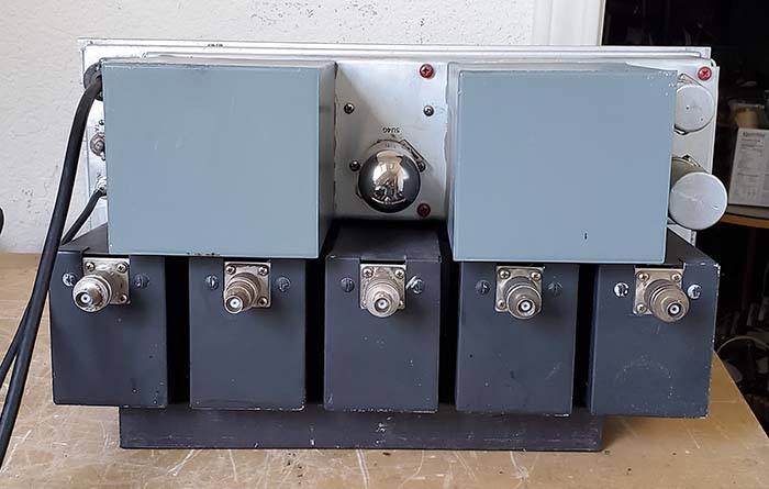
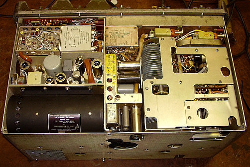
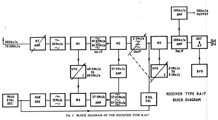
The Wadley Loop virtually eliminated frequency drift by using a combination of one fixed oscillators, one VFO and three mixer circuits. Note the block diagram shown to the right. First, a 1.0mc crystal oscillator feeds a harmonic generator that produces strong multiple 1mc harmonics that are used to create thirty selectable 1mc wide tuning ranges. This "comb" of harmonics are fed into Mixer 4 and combined with the output from the MC/VFO which tunes 40.5mc to 69.5mc. Simultaneously, the RF input signals are fed to Mixer 1 and combined with the output from the same MC/VFO output. The output of Mixer 1 tunes from 39.35mc to 40.65mc and feeds Mixer 2. Also simultaneously, the output of Mixer 4 goes to a 37.5mc amplifier, a bandpass filter and then another 37.5mc amplifier with its output also connected to Mixer 2. The "drift cancelling" happens because "Mixer 1 + the MC/VFO" and "the MC/VFO + Mixer 4" are the inputs to Mixer 2. If there's a frequency drift of, for example, 2kc in the MC/VFO, that frequency drift is seen in both Mixer 1 and Mixer 4 outputs (+2kc.) The Mixer 2 output is the difference of the two inputs (both +2kc) and still results in the 2-3mc IF. Since the drift is added (or subtracted) simultaneously to both inputs of Mixer 2, the resulting output doesn't change since the difference remains the same, thus the drift is cancelled (f+2 - f+2 = 0 drift.) Tuning the MC/VFO produces a Mixer 2 output that varies from 2 to 3mc. The KC/VFO tunes from 2.1 to 3.1mc and its output is combined with the 2 to 3mc 2nd IF in Mixer 3 producing a fixed 100kc 3rd IF.

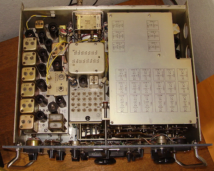
Although the Wadley Loop might be the "heart" of the RA-17, it's the elaborate Antenna-RF preselector circuit that allows the receiver's performance to be maximized for any frequency or antenna used. The preselector has a very Hi-Q and has six tuning ranges plus a variable tuning control. This allows exact tuning of the RF amplifier grid input which results in the absolute best transfer of antenna energy to the receiver's front end. A four-step attenuator can be selected if unusually strong signals are encountered. Racal's first receiver was designated the RA-17 and it was the first successful receiver to employ the "Wadley Loop" system for oscillator and conversion stability. The first British Royal Navy RA-17 receivers supposedly cost £ 300 each, an equivalent cost then of about $1500. The RA-17 was produced from around 1957 up to around 1973. The RA-17 was upgraded several times but also many variations were produced that were built for special purposes or to be used with other specific equipment. The RA-17 "C series" was generally built for North American use and has US-compatible parts.

As the Racal receivers became more and more popular with commercial and military users, a manufacturing facility was opened in the USA (one of many around the world) called Racal Communications, Inc., located in Silver Spring, Maryland. All of the receivers produced in the USA (or produced in the UK for North America) will have either an "A," a "C" or "6" (or combinations) added to the standard model number thus the RA-6117 is the "made in the USA" version of the RA-117 receiver (the RA-117 was a somewhat different version of the RA-17 that, for the most part, was produced concurrently with the various types of RA-17 receivers.) Production of the RA-17 and RA-117 runs up to about the mid-1970s at which time the RA-1217/RA-6217 solid state receiver was also in production having been introduced around 1967. Racal also produced many different types of accessory equipment for the RA-17, e.g., VLF/LF/MF converters, digital frequency readouts using Nixie tube displays, panoramic adapters, SSB adapters, diversity equipment, RTTY equipment, transmitters and many other devices. At one time, Racal employed 30,000 workers building many different types of electronics (not just radio equipment.) It was the third largest electronics firm in Britain and had facilities in 110 different countries. Calder Cunningham died in 1958 and, in 1966, Ray Brown accepted a political position in British Ministry of Defense, retiring from the company. After 1966, Ernest Harrison was in charge of Racal. The company also owned Decca, Chubb and Vodafone to name a few of their holdings. Several reorganizations and division sales occurred in the 1990s and, in 2000, Thomson-CSF (aka Thalen Group) purchased the bulk of Racal Electronics.

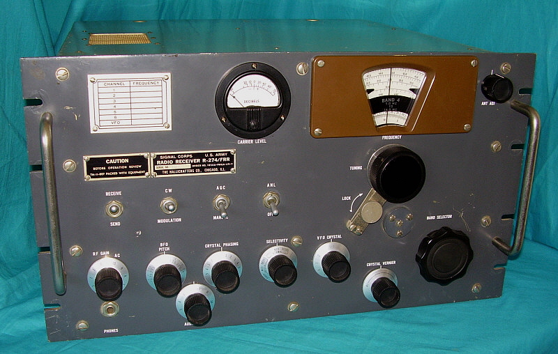
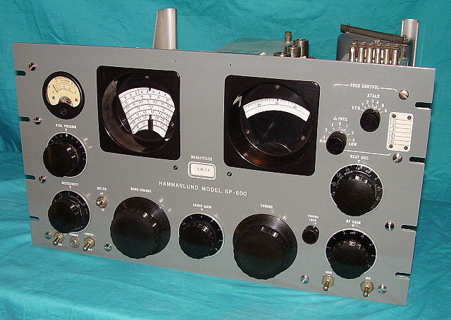
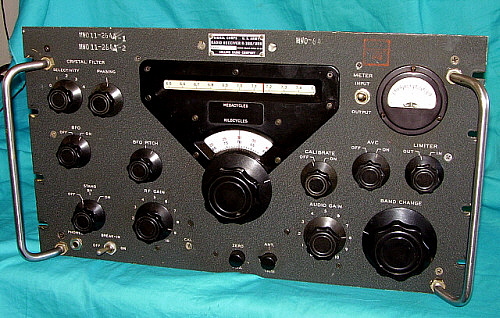
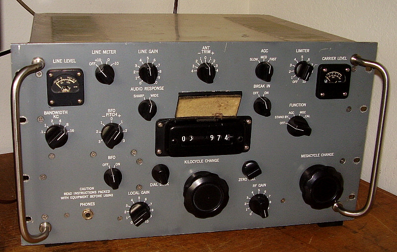
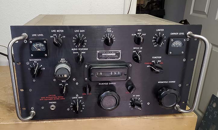
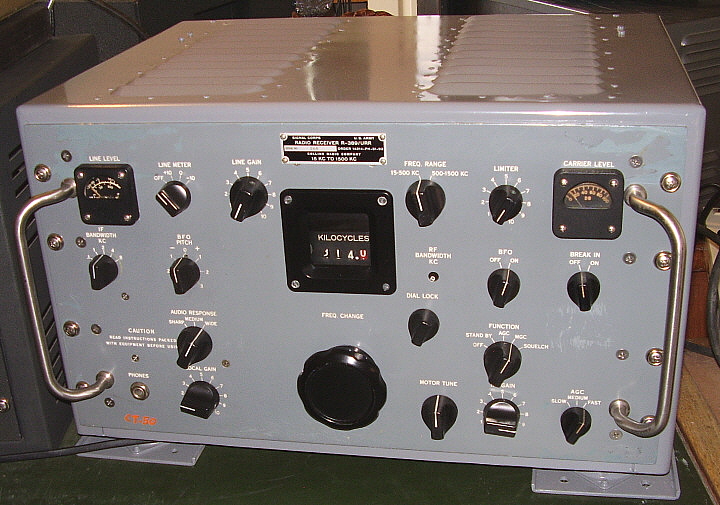
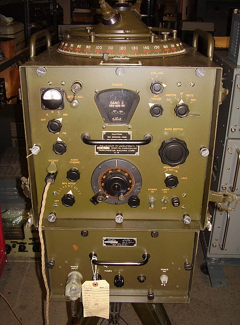
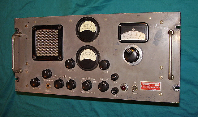
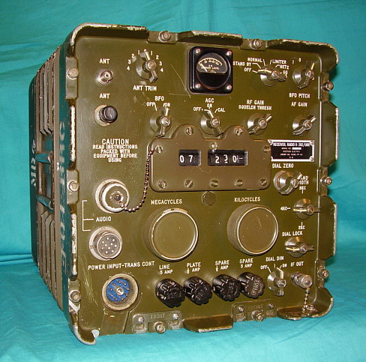
RA-17 Series/RA-17 C-12 aka AN/URR-501A - The RA-17 Series receivers comprise many slightly different versions depending upon the end-users specific requirements. There were over 40 different versions of the RA-17 built. All RA-17 receivers will have a suffix that further identifies what particular version the receiver belongs to. The "C- Series" were the North American versions of the RA-17 built in England but specifically for export. There were over 20 different versions of the C-Series of RA-17 receivers. Most of the different versions were for specific uses, such as Broadcast monitoring where the BFO circuit was eliminated and different IF bandwidths used or changes to allow operation with specific models of Racal accessories. Some C-12 versions were also identified as AN/URR-501A using the Army-Navy designation. Most C-Series hardware is UNF for USA compatibility. All of the tubes are USA types but two were eliminated, the GZ-34 rectifier tube and V-24 were replaced with solid-state substitutes. Other minor changes were to the 3.0Z ohm audio output that was increased to 1 watt. Also, a 10K 10W load was added to the B+ when the receiver was placed in Stand By and standard UHF and BNC connectors were used for rear-chassis connection auxiliary inputs or outputs (for accessory devices.) The preselector (panel ID: ANT TUNE) is actually an elaborate antenna tuning network that essentially provides a precisely tuned, Hi-Q output that feeds the RF amplifier grid. The preselector has six tuning ranges and a variable frequency "tuner." This tuned RF input can be bypassed in the "wideband" position which is then an untuned "wideband" fixed 75Z ohm input. The Antenna Tuning provides an increase in sensitivity by way of much better signal transfer to the RF amplifier grid and also the Hi-Q allows for better selectivity for the incoming signal which helps with reducing interference from strong, near-frequency, near-field signals. A five-step attenuator can be inserted into the signal path to reduce the input level to the RF amplifier if intensely strong signals are encountered. The RF amplifier is a standard pentode tube in RA-17 receivers but the C-Series used a cascaded dual-triode tube 6ES8. The 
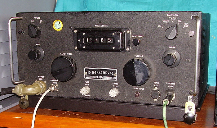
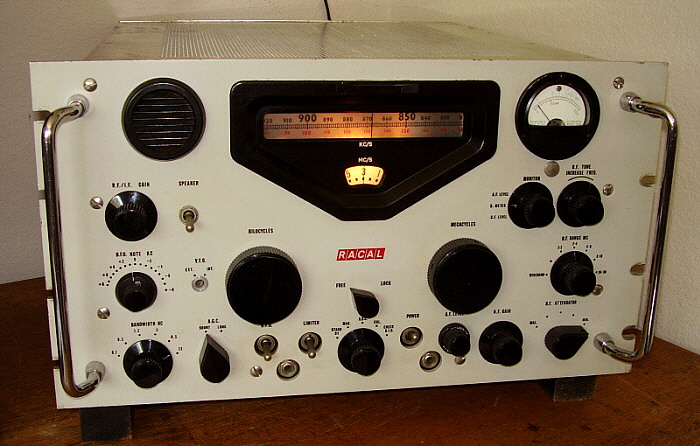
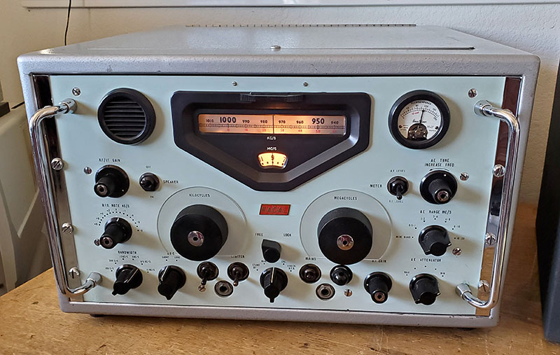
kilocycle tuning dial is a filmstrip type that is six feet long and spans 1000kc with a resolution of 1kc. When tuning the receiver, the dial index remains stationary while the numerical dial scale moves behind the index in a linear fashion. The megacycle dial is circular and is read thru the lower window of the dial escutcheon. To readout the tuned frequency one has to add the megacycle dial setting to the kilocycle dial reading. If the megacycle dial is set to 11 and the kilocycle dial reads 854 then the tuned frequency is 11.854mc (as shown in the RA-17 C-12 photo above.) The black kilocycle scale is used while tuning from 1-30mc while the red kilocycle scale is used when operating with the optional MW-LF-VLF converter (10kc to 980kc.) The tuning system is super-smooth and very light feeling. The film strip is easy to read to at least 1kc accuracy. A 100kc Calibration oscillator is provided to assure frequency readout accuracy. The RA-17 used 23 tubes but since the GZ-34 rectifier tube was replaced in the C-series receivers with a solid-state rectifier the RA-17 C-12 uses 22 tubes. The RA-17 Series tunes from 1.0mc up to 30mc in 30, one megacycle wide tuning ranges. Tuning from .5mc to 1.0mc is possible but with noticeably diminishing performance as the frequency is tuned lower within that range.

The use of triple-conversion and the drift reduction Wadley Loop provided solid stability. The normal C-Series bandwidth was selectable from 13kc down to 100hz in six positions. Last IF operates at 100kc with rear chassis outputs available. Selectable fast and slow AVC and a Noise Limiter were provided. A standard diode detector was used but the BFO injection is sufficient to allow easy demodulation of SSB signals. Several types of audio outputs are available at the rear connector terminals. BNC connectors provide IF output, 1MC output and RF input (for the LF converter and other compatible accessories.) UK versions only had a two-position 
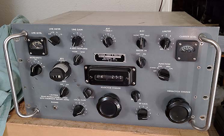
meter function (toggle) switch. The "C" versions had a three-position switch 
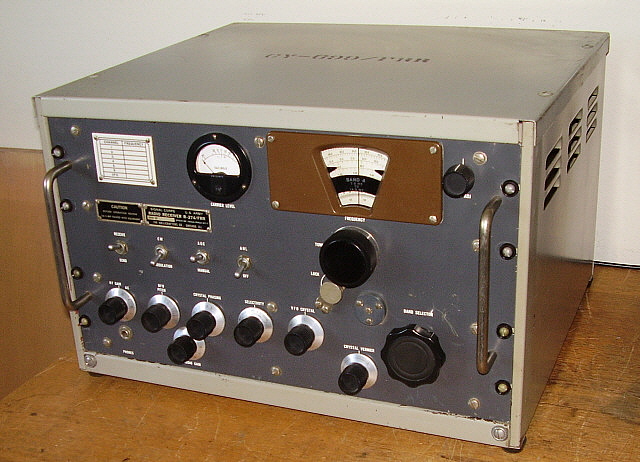
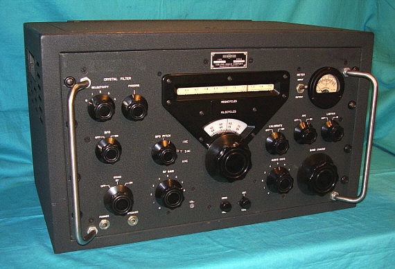
allowing RF level, S-meter and AF level functions.

Most of the RA-17 side panels have a slope beginning about halfway back and the top cover also slopes at the rear half of the receiver. The front panel is steel and is the standard 10.5" x 19.0" but the receiver depth is 20.5" which is considerably deeper than any USA-made receivers. The panels on the RA-17 receiver were originally supposed to be British Admiralty Gray (or battleship gray) but most encountered seem to be a light greenish color. Many RA-17 receivers panels were equipped with panel "scuff protectors" that mounted behind the Kilocycle and Megacycle tuning dials. These were normally made from clear plexiglass and protected the panel from "fat finger" syndrome that usually left the paint worn off in a "ring" around the knobs. The RA-17 C-12 shown above and right has opaque black "scuff protectors" installed. Apparently, this type could be installed if the panel already had "wear-rings" since they hid any damage and prevented any further damage. Since these type of protectors aren't transparent the covered nomenclature is engraved into the white-on-black plastic material. The MC and KC tuning knobs along with the five "non-winged" smaller knobs have a collet-type of grip on the shaft. Knob removal requires using a hex wrench to loosen the chrome nut at the center of each knob. These collets shouldn't be over-tightened when reinstalling these knobs.  


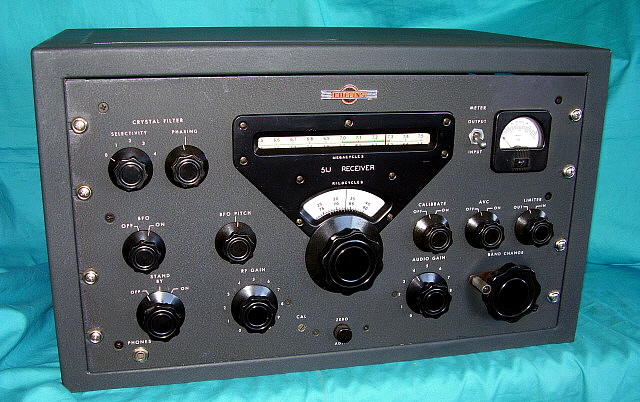
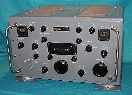
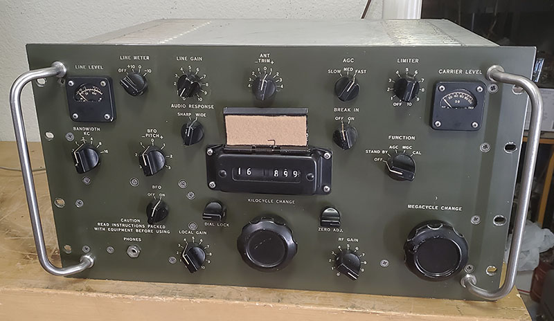
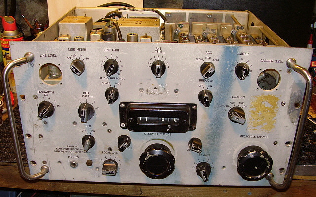
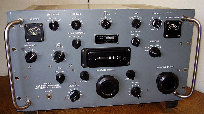
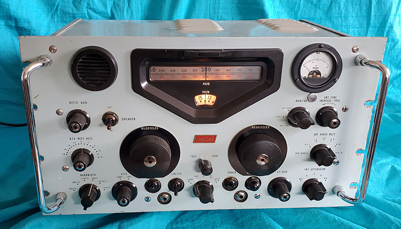
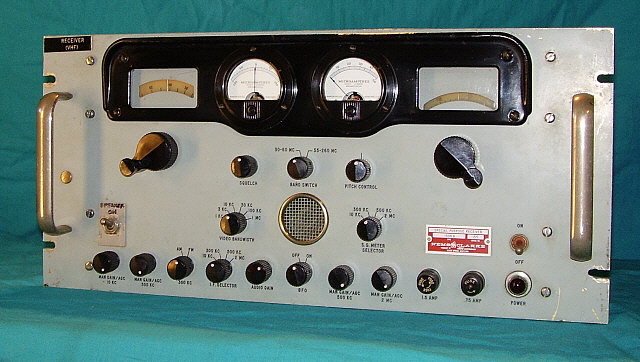
RA-6117   SN: 193  from 1966
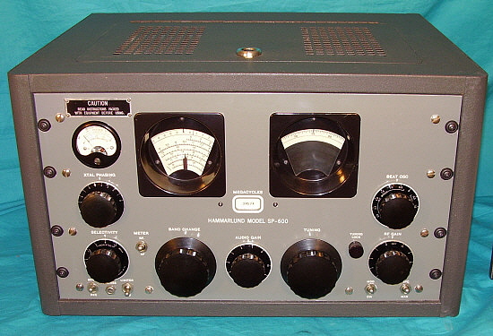
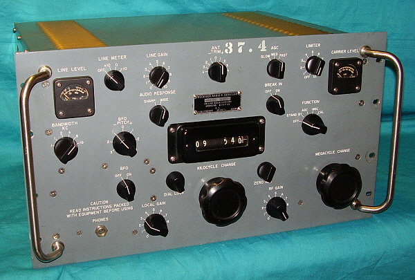
RA-117/RA-6117 - The RA-117 was introduced somewhat later than the RA-17 but for the most part was built along side that receiver. It's a slightly different receiver than the RA-17 and was developed to allow more of a variety of auxiliary equipment to be interconnected and operate with the receiver (such as the MA-79G exciter.) The RA-6117 is a version of RA-117 built in Silver Spring, Maryland, USA by Racal Communications, Inc. It's almost identical to the RA-117 but using all standard USA manufactured tubes. Most of the hardware is also standard US threads and sizes. USA-style knobs are used on the RA-6117.

Like the RA-17, the antenna preselector circuit can be set to "wide band" which is an untuned 75Z ohms input or the six-step frequency ranges can be selected and peaked for maximum response for the particular frequency and antenna in use. There is also a step-attenuator provided for coping with very strong signals but still being able to retain the tuned selectivity that the R.F. TUNE (was ANT TUNE on the RA-17) provides. The RF amplifier uses a cascaded dual triode tube (6ES8.) The Wadley Loop front-end was basically unchanged but the RA-117 did add an extra conversion-IF amplifier stage after the 2-3mc IF bringing the total conversions to four. The four conversion consisted of a tunable 40.65-39.35mc, a tunable 2-3mc, a fixed 1.6mc and a fixed 100kc. The additional conversion used a slightly different type KC-VFO (tuned 3.6mc to 4.6mc rather than the 2.1mc to 3.1mc VFO of the RA-17.) The KC-VFO/Mixer operated into a fixed 1.6kc IF which was then converted (crystal oscillator/mixer) to a fixed 100kc IF. The 3.6-4.6mc KC-VFO also featured external input and outputs to allow the RA-117 tuning to control (or be controlled) by other devices. VFO selector switch is on the front panel next to the Kilocycle tuning knob.  

IF bandwidths from 13kc to 100hz, Fast and Slow AVC, three position switch allows the meter to act as an RF signal level, AF level or S-meter, standard envelop detector - no product detector are features provided. Several BNC inputs/outputs are provided for External VFO, various Oscillator Outputs, 100kc IF Output along with terminals for several 600Z ohm outputs and a 1W 3.0Z ohm output.

A separate audio output (600Z ohm) with an Audio Level control on the front panel that has its own output transformer and operates separate from the standard receiver audio output. This output was for driving a data device, an audio input RTTY converter, for example. The small built-in speaker can be switched off if a larger speaker is desired (connecting to the 1W 3.0Z ohm output works best.) RA-117 receivers use 25 tubes. RA-117 Series tunes 1-30mc in 30 bands. Also, .5-1mc tuning with noticeably diminished performance as one tunes lower in frequency within this range. The RA-6117 front panel color is usually cream color with black nomenclature. Scuff protectors aren't usually found on RA-117 receivers as the EXT/INT 
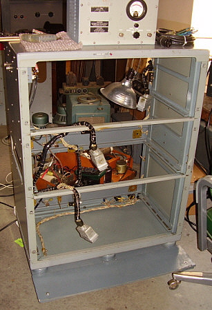
VFO switch interferes with proper positioning. Although the RA-17 and RA-117 panels are standard 10.5" x 19.0" the receiver's chassis is quite deep at 20.5" which, of course, won't fit into any standard American cabinets. There were cabinets available that were specifically for the RA-17/RA-117 and only increase the overall receiver foot-print an inch or two. Other after-market general purpose cabinets that have the necessary depth are usually very large and increase the overall receiver size substantially. However, most receivers usually will have their dust covers and, like the R-390A, look quite nice setting on a table "sans cabinet."
Performance RA-17 and RA-(6)117 - With either the RA-17 or the RA-(6)117, sensitivity is first rate as these receivers can "hear" just about anything that's being transmitted, depending on the listener's location and receiving conditions. Best reception results will require a good, resonant frequency or "tuned" antenna system and very careful tuning of the RF antenna preselector. This circuit is very Hi-Q and the tuned "peak" is very sharp. The signal gain with precise grid input tuning to the RF amplifier is impressive. "Wideband" can be used with strong, near-field signals, like AM BC stations. The Attenuator can be used to quickly reduce strong signals while still keeping the preselector tuned. The filmstrip dial is easy to read and is accurate "to the kilocycle" if the CAL oscillator is used. IF Bandwidth selections will usually be 3kc or 6kc for normal listening. SWBC stations sound fine on 6kc and if they are particularly strong and transmitting something interesting the 13kc bandwidth provides excellent reproduction. The 13kc could be used on AMBC in the 1000kc to 1700kc part of the band if there was something worth listening to. Performance below 1000kc is okay for about 100kc or so, then it begins to degrade. The bandwidths of 1.2kc, 500kc and 100kc can be used for CW signals. For reducing adjacent frequency SSB signals while in the AM mode, "off frequency tuning" is the easiest and most effective defense. Speaking of SSB, the BFO coupling is via a 45pf capacitor but that provides sufficient injection for excellent SSB demodulation. In some cases, the RF/IF Gain might have to be reduced to clear up distortion on particularly strong SSB signals but most average strength SSB signals demodulate fine with the IF/RF Gain fully advanced and the AVC on. Upper and lower sideband can be selected by using the +/- BFO setting (which is like the R-390A.) Use + BFO settings for LSB and - BFO settings for USB. There are three low power 600Z outputs for driving data devices. For the best audio reproduction use a good quality external speaker connected to the 3.0Z ohm output. The 3Z ohm Audio Output is 1 watt on the "C" versions and provides more than adequate drive. Shortwave BC stations and AMBC stations that are transmitting quality programming will sound incredible. There are slight differences between the British RA-17 receivers and those RA-17C receivers built in England for the USA or NATO. Also, there are some differences between the RA-17 Mark III versions and the earlier Mark II receivers. Performance for all versions is nearly identical although bandwidths, audio power, BFO tuning, meter functions and other minor variations will be encountered with the different receivers.
 

For more details on RACAL receivers, company history, details on the RA-237-B LF Converter, details on the RA-6217E Solid State receiver go to "RACAL - British High Performance Receivers" use "Home/Index" for navigation.


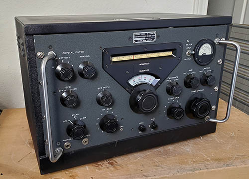
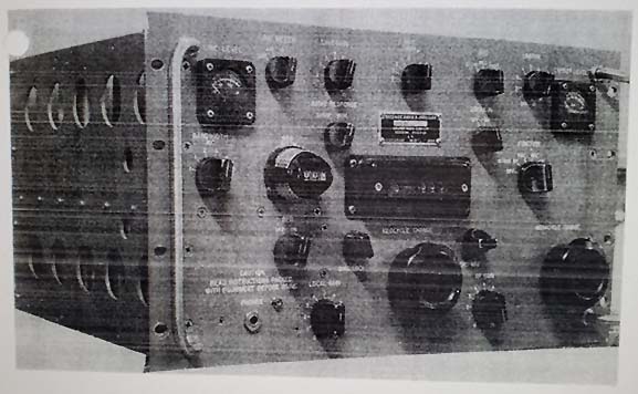
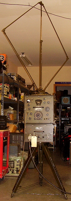
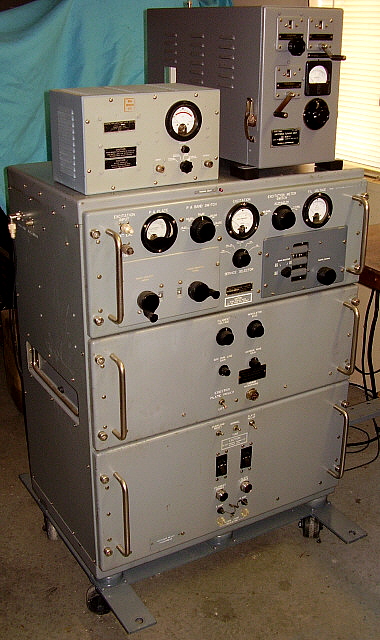
RA-17L Mark III in original military RACAL table cabinet from 1964

The plastic "scuff protectors" were to prevent "fat finger syndrome." That happened when the operator's fingers gripped the tuning knob, overlapping the entire grip-area of the knob and rubbed the finger tips against the front panel. Over time, this would wear the paint off of the front panel (usually a circular ring of missing paint surrounding the tuning knobs.) The black "scuff protectors" on the RA-17C-12 were installed to hide "fat finger damage."


The Technical Materiel Corporation - GPR-90RXD

The Technical Materiel Corporation was founded by Ray DePasquale in the mid-1950s to provide commercial and military-grade communications equipment along with high-quality communications receivers for radio amateurs. TMC's most popular product (along with the CV-591 SSB Adapter) was the GPR-90 receiver that was produced from 1955 up to about 1962. It was a $400 to $500 receiver that was primarily designed for use by hams. Within a short time, the military decided that they too wanted some GPR-90 receivers with some variations to the design. The military wanted TMC to add a separate crystal oscillator (HFO) with ten selectable crystal-controlled channels to the GPR-90 along with changing the antenna input impedance from selectable 300Z ohms or 75Z ohms to a fixed 75Z ohm input. The first RF amplifier was also changed to a standard tuned grid input rather than the grounded grid input used in the GPR-90. Additionally, inputs for an external LO and external BFO were provided. These receivers were designated as GPR-90RX. TMC also built a diversity version of this receiver that provided accessible Diode Load and AVC lines for interconnecting two (or more) receivers for diversity reception. These receivers were designated as the GPR-90RXD. There was also a GPR-91RXD that provided a 15kc selectivity bandwidth for four channel independent SSB reception or multiple channel RTTY reception (the GPR-90RX[D] had a 7kc bandwidth.) The military versions also had military designations with R-825/URR used for the GPR-90 and with the RX and RXD(?) versions usually identified as R-840/URR.

All of the GPR-90 receivers are double preselection on all bands (two TRF amplifiers) and dual conversion on the top three bands (5.4mc to 31mc) with the first conversion at 3.995mc and the second conversion at 455kc. Three IF amplifiers are utilized and the Detector is a standard envelope type using a 6AL5 dual diode tube. Audio output uses a single 6V6 tube and the output transformer provides 4, 8, 16 and 600 Z ohm impedances. 15 tubes are used in the GRP-90 while 16 tubes are used in the RX and RXD versions (adding the 6AG5 Selectable Xtal Oscillator.) A matching loud speaker was available for the GPR-90 receiver. All RX and RXD versions were rack-mounted receivers.

The BFO circuit in the GPR-90 receivers is lightly coupled with only a few pico-farads of capacitance to prevent "masking" of weak CW signals. This, in addition to the standard envelope detector, makes reducing the RF gain control necessary for proper signal to BFO injection ratio for either CW or SSB reception. For improved SSB reception, TMC offered a "GPR-90 matching" table-top SSB adapter, the GSB-1. It's also possible to use the rack-mounted CV-591 SSB adapter with the GPR-90 receivers. Some of the rack-mounted SSB adapters were designated as "MSR" units (Mode Selector - Receiving) and these are similar in design, appearance and use to the CV-591. The GPR-90RXD manual specifies that the MSR-6 can be used for enhanced SSB reception. See section below on the TMC SSB Adapters. 

In 1963, the GPR-92 was introduced but only 115 were built before the model was discontinued. TMC continued to expand in the 1960s with several companies located in many different states (Mamaroneck, New York is the headquarters location.) TMC provided the military with several types of transmitters and other types of communications equipment. Eventually, Neil DePasquale (Ray's son) began running the company. While all of their competition either went out of business or were purchased by other companies, The Technical Materiel Corporation is still in business (although sparsely staffed) and is still run by Neil DePasquale.

The GPR-90 has a varied reputation based on the many subjective reviews that abound on the Internet. It's easy to find conflicting reviews about the receiver with some users rating the GPR-90 as an excellent performer while others feel the receiver is not up to TMC quality in either performance or construction. There was a tendency by many to compare the GPR-90 to the Collins R-390A receiver but the two receivers couldn't be more diverse in either design or selling price. Consider that the R-390A sold for well-over $2000 while the GPR-90 was $495. Even the GPR-90 manuals warn users that if they want "frequency meter" accuracy then they should buy a "frequency meter" and not ask the receiver to "double as both." Certainly a statement that illustrated TMC's frustration with comparisons of the GPR-90 to Collins' "frequency accurate" tuning systems. A fair comparison of the GPR-90 would be to the Hammarlund HQ-180 receiver. Both receivers were basically contemporaries and sold for about the same price for the same intended end-users. There's even a similarity in both receiver's tuning drive systems (rim-drive pinch-wheel) and in their front panel layout of using two dials separated by the S-meter. Both receivers have similar performance specifications. Certainly there's no argument that the GPR-90 is a physically beautiful radio receiver creation and it does present itself quite well in the ham station landscape. However, if you're expecting "Collins performance" out of a $495 receiver,...well, you'll probably be disappointed when using the GPR-90 in an actual "on the air" QSO. Like the HQ-180, the GPR-90 is an excellent SWL receiver.

The GPR-90RXD version does perform somewhat differently than the standard GPR-90 since it has a fixed 75Z ohm input and has other changes within the chassis for diversity reception and other various purposes. Still, the RXD is very sensitive and has probably the best Crystal Filter circuit of the time (so does the standard GPR-90.) Dial accuracy is very good considering that it is an analog readout that is limited by its resolution. Proper alignment is critical in many receiver designs and certainly the GPR-90s will perform best when in good condition with no defective components and with a fresh IF/RF alignment. 

Technical Materiel Corp. -  SSB Adapters  -  The Technical Materiel Corporation designed and built several variations of their popular CV-591 SSB Adapter that were compatible with many types of receivers used by the military and commercial users. The receiver used had to provide an IF output that was then connected to the input of the SSB adapter. TMC supplied SSB adapters for the popular IFs used in the 1950s and 60s (455kc, 500kc and 200kc.) Shown in the photo below is the GPR-90RXD set-up with the TMC MSR-6 Mode Selector - Receiving (SSB Adapter.) Both the receiver and the adapter are assigned the same serial number (126) which implies that they were sold, installed and used together as a "set" (although originally "rack mounted.")    >>>

>>>   All of the TMC SSB adapters work in a similar manner. The adapter circuitry down-converts the incoming IF from the receiver, 455kc for example, to a lower frequency (17kc) and then mixes a BFO to provide product detection. Bandpass and Low Pass LC filters were utilized to increase selectivity. A crystal-controlled oscillator is used for the first conversion (receiver IF to 17kc) and also a VFO called "bandspread" (manual select) is provided. Crystal frequencies are 17kc above and below the IF to provide selectable Upper or Lower sideband. Sideband selection uses a push-button that actuates a selector relay which also operates the "U" and "L" lamps accordingly. The AVC circuit operates on the incoming signal from the receiver and provides a fairly constant level of signal and has selectable fast and slow AVC action. Audio output is 8.0Z ohms or 600Z ohms from a single 6AQ5 tube. Although specifically for SSB reception, CW signals can also be received. Also FSK can be received. Additionally, the ability to select the upper or lower sideband of an AM signal or to receive an AM signal in the "exalted-carrier" mode (AM + zero-beated BFO) is available. Exalted carrier reception usually improves weak, difficult to copy AM signals. There are several remote operation options available including remote sideband selection or detection along with remote BFO operation and tuning. Some versions were specifically designed to utilize remote inputs from specific TMC-built receivers. 

Once connected to the particular receiver, if only the SSB converter audio output is utilized then the user will not have the availability of the receiver's circuitry down-stream from the last IF stage, usually the noise limiter and the receiver's audio output circuitry. Two separate speakers can be used with one connected to the standard receiver audio output and another speaker connected to the SSB adapter's audio output. With the dual speaker set-up, the user can choose the receiver's audio output for AM signals (probably better fidelity) and the SSB adapter's output for SSB or CW signals (virtually distortion-free SSB.) Single speaker operation can be achieved by paralleling the adapter's 600Z output with the receiver's 600Z output (Z is then 300ohms.) Then connect 4.0Z ohm speaker to receiver's 8.0Z ohm tap.

TMC offered the CV-591A and CV-657A (and many other variants) for the military. The CV-591A utilized 455kc IF input while the CV-657A utilized 200kc. The MSR series went from MSR-1 thru MSR-9. MSR-3 utilized 200kc IF input while the MSR-8 utilized 500kc IF input. All other MSR numbers utilized 455kc IF input. The MSR-1 and MSR-4 are also considered CV-591A units.


National Company, Inc. - NC-400

The NC-400 was introduced in 1959. It was obvious from the astounding list price of $895 (2023 equivalent is $9200!) that the intended customers were going to be commercial users along with military and government purchasers. Many of the features of the NC-400 were necessary for commercial-military applications but weren't required by or even of interest to the ham users. The five, selectable, fixed-frequency, crystal-controlled receiving channels or the diversity options were certainly for military or commercial use. The crystal-controlled BFO option or the IF output (both for RTTY) were other features not normally found in a ham receiver. Production estimates vary widely - from an incorrect low estimate of several hundred receivers up to perhaps as high as 1000 receivers (highest SN seen here was in the 600s.) Probably less than ten percent of production went to the "well-to-do" hams and SWLs who could afford the "stratospheric" price. The remaining receivers were sold to commercial and government users. Among the more commonly mentioned government users is the FBI where the receivers were installed in some field offices for various purposes. Certainly other government users and the commercial users found the NC-400 filled their requirements and the exorbitant price was paid either by tax-payer dollars or company requisition funds. The NC-400 was available up to about 1963.

The NC-400 is a double pre-selection receiver (two TRF amplifiers) and is also dual conversion above 7.0mc. Seven tuning ranges cover from .54mc up to 31mc. The band spread dial is calibrated for the HF ham bands with a logging scale provided for general coverage. The conversions take place at 1720kc and 455kc of which the latter is derived from a crystal-controlled oscillator. There is a "plug-in" feature for the crystal filter assembly which can be removed and replaced with an optional mechanical filter assembly that allowed the user switchable access to a maximum of three different mechanical filters for bandwidth selectivity. The LO tube heater is operated from a higher heater voltage winding on the power transformer that has the voltage dropped thru a 4H4C current regulator to provide stable heater voltage regulation. A dual triode 6BZ7 is used for the LO and for the switchable Crystal Oscillator. The three IF amplifier stages actually are dual IF strips that utilize the same amplifier tubes. One IF strip is for SSB and provides 14 tuned circuits to achieve a fixed 3.5kc bandwidth. Upper or lower sideband can be selected with the bandwidth switch as "SB1" or "SB2." The operator can also select other bandwidths for the SSB mode but the BFO may require a slight adjustment other than using the SSB arrow on the BFO knob. The Crystal Filter can't be selected in SSB. The fixed 3.5kc bandwidth was thought at the time to be ideal for SSB and the switch sideband selectability was to ease tuning difficulties in the SSB mode of reception. In CW, the crystal filter is switched into the circuit instead of the first set of SSB IF transformers after which the CW signal continues thru the first IF amplifier tube and thru the remaining SSB IF strip. In the CW mode, AVC is not utilized and the RF must be manually adjusted. It is, of course, possible to tune in SSB signals in the CW mode to take advantage of the Crystal Filter and manual RF gain control, if desired. AM signals are switched to the second IF strip that utilizes six tuned circuits and provides switchable bandwidths of 16kc, 8kc and 4kc. The VS (Very Sharp) provides 3.5kc bandwidth with ten tuned circuits plus the VS position selects the crystal filter to provide another fives steps of selectivity down to 150hz bandwidth. SSB and CW signals are routed to a Heterodyne Detector/BFO that is essentially a product detector. AM signals are routed to a diode detector. Tone control is a two-position switch that was only intended for noise reduction. The noise limiter is also a basic clipper type. The audio is 1 watt output from a single 6AQ5 tube with either 600 Z or 3.2 Z available. The matching loud speaker was specified as the NTS-2 (also specified for other National receivers of the time.)

Today, most vintage ham gear enthusiasts tend to believe that the NC-400 was "over-priced, over-rated and used cheap parts." Another common opinion is that the NC-400 is one of National's worst-looking receivers. However, the NC-400 can perform quite well if it's in good condition and properly aligned. It has sensitivity and stability that was competitive with any of the communication receivers of the time. However, sensitivity isn't all that's required for reliable radio communication. National wasn't alone in continuing to produce a dial readout system that couldn't resolve the tuned frequency "to the kilocycle" as Collins equipment could. The NC-400 dial resolution is vague and if you have the optional crystal calibrator you can then find markers on 1000kc or 100kc but most of the scale index markers are in 10kc increments so anything more accurate than 10kc is just guesswork.

Some of the parts used for the NC-400 seem inconsistent with its high selling price. Most of the knobs appear to have been "leftovers" from old National television sets with these knobs having flat-springs inside the plastic hub and then pushing onto half-shaft controls. National couldn't even install band-in-use indicators that actually worked and, even if they did work, consisted of crude pointers that were supposed to align with the band-in-use scale. Out of the cabinet, the chassis is moderately flexible and that can't be good for alignment which, of course, has to be performed out of the cabinet with the chassis on its side. The front panel and cabinet design must have been conceived by an interior decorator since the paint scheme uses three different shades of gray in both smooth and wrinkle along with black winkle finish with chrome trim strips on the sides of the cabinet. Then there are both gray knobs and black knobs along with four small aluminum knobs. National's advertising artwork never flattered the NC-400 and, for some reason, the receiver is just not photogenic. It will always look better "in person" than it does in photographs.

Ownership and actually operating the NC-400 goes a long way toward one's overall appreciation of the NC-400 and certainly its performance is at the forefront of that appreciation. The NC-400 can pull in signals quite well, especially after a careful alignment. The audio quality is a pleasant surprise considering it's just a single-ended 6AQ5 that's producing the very natural sounding reproduction. However, the Tone switch is next to useless since it just reduces the high audio frequencies slightly. For the best audio reproduction, use a good quality, moderately large diameter speaker, 10" to 12" is sufficient, installed in a decent housing and the NC-400 audio will sound great. When (or if) you get used to its appearance (and its quirks) the NC-400 becomes a fine station receiver.

Although a few collectors might consider the NC-400 a "ham receiver" due to some of National's advertising, I have it listed here in the commercial equipment page because most of these receivers were sold to government and commercial users. The particular NC-400 (SN: 543 0006) shown above was a commercial receiver that was owned by radio-tv station WHAS in Louisville, KY. Many of the large radio and tv stations would have their own repair facilities and technician staff. It's likely that the NC-400 was in that environment at WHAS since it was obviously used very little and luckily it was never worked on by their staff technicians or ever had any ham-mods incorporated. It's really a pretty nice performer.


Siemens AG  -  E-311-E1

Siemens is a very old and very large German conglomerate that manufactures many different types of products. The company was founded in 1847 by Werner von Siemens and Johann Halske to sell their non-Morse-type telegraph system. The Siemens telegraph was installed in many locations throughout Europe. Siemens continued to grow through the nineteenth century adding electric trains and light bulbs to name just a few types of products offered. Many varied companies were added to the Siemens conglomerate during the twentieth century and, even today, Siemens continues to add new products, including medical equipment, to the conglomerate. Siemens employs over 300,000 people world-wide and is a major supplier of medical equipment and many other types of products.

The Siemens E-311-E1 was produced from 1959 to 1961. It's a seventeen-tube, triple-conversion superheterodyne that tunes from 1.5mc up to 30.0mc in five tuning ranges. The IF conversions are a tunable 1300kc to 1400kc IF followed by a 370kc IF that can be tuned by an interpolator and finally a fixed 30kc IF. The receiver is comprised of seven modules that interconnect although some hard-wiring is also used. The modes receivable are A1(CW,) A3(AM) and A3a(SSB.) When AM is selected the receiver automatically shuts off the BFO and uses different filters for 6kc-wide DSB-AM reception. When SSB is selected the BFO is automatically turned on and the Sideband selection switch enabled allowing the user to select USB or LSB. The meter can read either audio output or RF signal voltage. The selectable IF bandwidths are only available on CW or AM and are 3.1kc, 1.5kc, 0.5kc and 0.15kc for CW and 2X for AM. SSB bandwidth is fixed at 3.5kc. Two time-constants of AGC are provided, 2.0 sec decay and 0.2 sec decay. The built-in speaker can be turned off by pushing in the AF Gain control to actuate the switch. An external loudspeaker (5Z ohms) can be connected via the front panel phone jack. 600Z ohms LINE is also available via a front panel phone jack as is the headphones jack. A phone jack is provided for accessing the IF to drive data devices (RTTY.) Also, a phone jack allows connecting an optional LW adapter. A Noise Limiter control is also provided. A Squelch control is also provided but, since it's a carrier-operated circuit, it only functions in the AM mode. The front panel nomenclature is bi-lingual in that both German and English indicate control function.

Extreme dial accuracy is provided by dual frequency indicators. The arc-dial reads megacycles while the vertical dial reads kilocycles. If the 100kc SYNC circuit is turned off then the receiver can be coarse tuned using the left-hand tuning knob. With the 100kc oscillator set to SYNC then the coarse tuning has to be set to a 100kc position where the 100kc "lock" lamp indicator will stop blinking and turns on continuously indicating a 100kc frequency "lock." Then the Fine Tuning knob will tune that 100kc bandwidth via an interpolator circuit tuning the second IF providing an accuracy of 100hz on the KC dial. For example, if 14.100mc was set on the Coarse tuning (and in lock) then the Fine tuning would tune from 14.100mc up to 14.200mc. Each 100kc part of the spectrum selected by the Coarse tuning will be tuned by the Fine tuning when in 100KC SYNC. If extreme accuracy isn't necessary or if wide coverage of the spectrum is desired then the Sync can be set to OFF and then tuning can be accomplished with the Coarse tuning with the Fine tuning set to 00. Since extreme accuracy was necessary in some applications, the 100kc oscillator and the Interpolator oscillator operate in special oven temperature-controlled ovens. Green indicator lamps show if the ovens are powered. When the ovens are at temperature the green lamps cycle "on and off" as the temperature is maintained.  The Calibrator provides a 400kc marker that corresponds to special markers on the megacycle dial. There was an optional 1kc spectrum oscillator that functioned like the 100kc SYNC and provided a 1kc marker for extreme accuracy in determining actual frequency of a received transmitted signal. The 1kc spectrum oscillator is not installed in the "E1" version of the receiver.

The seventeen tubes used in the E-311-E1 are made up of only four different types of tubes, 3 - EF93 (6BA6,) 5 - ECH81 (6AJ8) and 8 - EC88CC (6922.) The 85A2 (0G3) regulator tube accounts for the seventeenth tube. All inputs and outputs are located on the front panel. The rear of the receiver is entirely enclosed when mounted in its cabinet. The receiver shown is mounted in the standard desk top case. There was also a shock-mount type case available. Weight is 55 pounds. The original selling price of the E-311 was 15,000dm (approximately $3750 in 1960.)

Performance Notes:  The E-311-E1 is an unusual receiver that has impressive sensitivity and excellent dial accuracy. "SYNC" tuning can be cumbersome due to the 100kc tuning range limitations but one can always "random scan" the entire selected tuning range turning off the SYNC and using the Coarse tuning. I find that SYNC-off is best for SW BC listening since I can cover the entire SW band quickly. SSB reception is very good although the fixed 3.5kc bandwidth might be a problem in a crowded band. I've only experienced SSB QRM that made copy difficult once, so 3.5kc works fine most of the time. CW has bandwidths available down to 150 cycles, so no problems there. 1.5kc bandwidth works best on CW most of the time. AM is actually quite good since the bandwidth "doubles" so the 3.1kc bandwidth is actually 6.2kc. AM signals sound very good. I'm using a separate loudspeaker that is 8" diameter (4Z ohms) and the reproduction is much better than the panel speaker for most reception.

I've used the E-311-E1 as a station receiver paired with an ART-13A transmitter and have found it to perform very well on 75M AM. It's selectivity in the A3 mode and with the 3.1kc bandwidth selected should be a little over 6kc and it does seem at least that wide since, when adjacent SSB QRM is encountered, it's possible to tune "off freq" by up to 4kc on either sideband and still recover enough audio for good copy. The Noise Limiter works particularly well in the A3 mode and doesn't distort the audio. The BIG problem is that there's no type of standby, local or remote, for the receiver. The manual states that the Squelch control can be used to mute the receiver during transmit but that doesn't seem likely to work (and it doesn't - maybe a translation error.) The ART-13 vacuum T/R switch provides antenna isolation during transmit but the E-311-E1 RF gain has to be reduced to zero to avoid feedback during transmit. Another solution would be to use the ART-13 sending relay contacts (using NC on xmit) to short the external speaker for mute (but I haven't tried that,...yet.)

UPDATE: I've found a very good use for the E-311-E1. It's set-up as the monitoring receiver for the upstairs workbench.


Commercial-Military VHF Receivers

Nems-Clarke, Inc.  -  1302 Special Purpose Receiver

Allen Clarke started in the electronics design business in the 1940s and by 1951 had a small electronics design business. NEMS was an acronym for National Electric Machine Shops, a name chosen by NESCO, National Electric Supply Company, when they incorporated in 1937. NESCO goes back to 1899 and the company was involved in radio manufacturing very early with many contracts assigned to them in WWI and after. NEMS and Clarke merged in 1955 as Nems-Clarke - specializing in high-end commercial-military radio equipment. All (?) Nems-Clarke receivers operate in the VHF and UHF part of the spectrum that was then being used in part for telemetry from some kinds of missiles and for other military and quasi-military purposes. Later Nems-Clarke receivers monitored Russian missile launch telemetry. The 1302 Special Purpose Receiver is a VHF AM/CW/FM receiver that utilizes a Western Electric 416A Planar Triode tube in the front end. The 416A operates at a very high temperature and is cooled by a small forced-air blower. The receiver tunes from 53mc up to 262mc in one continuous coverage tuning range with a 0 to 35 scale for logging. The tuning dial is not illuminated. Behind the grille on the left side of the panel is the built-in four inch speaker. The 1302 was designed to operate with a matching Spectrum Display Unit, (SDU) or Panadaptor.  The upper zero-center meter is for tuning FM and the lower meter shows relative signal strength and can be used for tuning AM signals or measuring relative FM signal strength. The 1302 was primarily used for surveillance by several different government users. Later versions of the 1302 use a different front-end tube (7007) and are styled more like the Nems-Clarke receiver shown below.


Nems-Clarke (Vitro Electronics) - 1306-B Special Purpose Receiver

Nems-Clarke was purchased by Vitro Electronics in 1957. Nems-Clarke/Vitro continued to produce Special Purpose Receivers for surveillance and telemetry that were used throughout the late fifties and sixties. The 1306-B Special Purpose Receiver is a 29 tube AM-FM-CW receiver that was usually operated with a SDU-200-6 Spectrum Display Unit (panadaptor.) The receiver tunes 30mc to 60mc and 55mc to 260mc with separate dials for each band that are only illuminated when in use. Selectable IF bandwidths, selectable IF AGC/Manual Gain controls, Squelch and a BFO with variable Pitch Control are provided. The zero-center meter provides accurate tuning for FM signals while the right hand meter measures signal strength. The built-in speaker is a very small "communications quality" unit that is located behind the screened cover. A 600 ohm audio line is provided on the rear panel can provide excellent audio quality to a matched loud speaker. The "SPEAKER" switch is a factory modification that replaced a PHONE jack with a switch to silence the panel speaker. Many of the Nems-Clarke surveillance receivers were used to monitor Russian missile launches and analyze data transmissions along with any voice traffic. The 1306-B is a great performer with an impressive appearance.


Federal Telephone & Radio Corp. for U.S. Navy - R-482/URR-35  a.k.a.  AN/URR-35

The AN/URR-35 is a VHF-UHF receiver that covers 225mc up to 400mc in one continuous tuning range. The circuit is double conversion with the first conversion at 18.6mc and the second conversion at 1.775mc. The URR-35 is an AM only receiver but it can also receive MCW signals (modulated CW.) It is a manually tuned vacuum tube receiver that also has provisions for a single frequency, crystal controlled fixed-frequency operation. Squelch is adjustable with the controls underneath the right side door. The left side door provides access to the crystal and selector switch. The left meter reads signal level and the right meter reads audio output level. Controls (l. to r.) are Manual Tuning, Dial Lock, Dial Lamp Dimmer, Noise Limiter, Output Gain, Power ON, Audio Output (standard phone jack under the toilet set cover.) Power input, Antenna Input, Audio Output are accessible via a plug-in rear module that is generally mounted to the rear of the cabinet. Shock mounts are integral to the cabinet and the receiver was usually supplied with a kit for rack mounting if desired. The contract number on the receiver shown in the photo is NObsr57142 probably dating from 1957. The receiver shown was rebuilt at the Philadelphia Shipyard in 1966. Serial number is 792 although the field change record tag on the front panel indicates serial number 1600 (which indicates that the receiver was installed into a different case at sometime.) Other contractors built the URR-35 besides Federal T & R.

Although this is a working URR-35, the 225mc to 400mc region of the RF spectrum is not overly-populated with AM signals. I was of the opinion that the URR-35 was only good for listening to static or maybe a VHF RF signal generator connected to the antenna input of the receiver. Luckily, fellow URR-35 owner Rex, KE7MFW (QTH - Yerington,NV,) discovered that the Fallon NAS uses AM on 318.50 mc for their pilot training exercises. Rex also reports that the receiver is very specific about the antenna used which must present a fairly good 50 Z ohm match. I use an 8" piece of 14 gauge wire inserted into the SO-239 antenna input and this seems to work well on 318 mc allowing me to copy the NAS training exercises quite well (although transmissions are typically sporadic and quite short.) Both Rex and I  have also heard some voice transmissions in the 270mc to 285mc region. Transmissions are brief and the length of time "on the air" minimal which means you have to keep tuning around until you happen to find a transmission in progress. Activity is sparse but with patience you'll hear some voice transmissions. For checking reception, there are a number of unmodulated carrier beacons in the spectrum covered by the URR-35 that are "on the air" continuously but without a BFO these are somewhat difficult to hear. I usually can tell they are present by hearing the background noise drop as the carrier is tuned and watching the input or output meters for an indication of tuning through the signal. As to the purpose of the beacons,...unknown.


Military Morale Receivers

Zenith Radio Corp.
for U.S. Army Signal Corps

R-520/URR  &  R-520A/URR


photo left: R-520/URR (H-500 Series TO)

photo right: R-520A/URR (600 Series TO)


Morale radios, that is radios specifically made for entertainment reception by military personnel, have been around since before WWII. It's not surprising that the Signal Corps wanted something for the soldiers to listen on during the Korean War. The Zenith Transoceanic was a very popular portable AM-BC and SW radio with Zenith cranking out well over one hundred thousand units by 1952. It seemed like a natural choice for a morale radio.

>>>  A few changes had to be incorporated into the basic H-500 style, five tube TO. A neon pilot lamp (a power on indicator) was added. The band selector switch information was color coded. Increased shielding was added. The black stag covering was replaced with a brown vinyl oil-cloth covering. Additionally, "USA" was stamped in Signal Corps orange paint on all sides of the cabinet and a metal data plate attached to the front below the latch. This was the R-520/URR "Transoceanic" that was produced for the Signal Corps. About 5000 units were built but by the time Zenith finished the contract and had shipped the R-520s out, the Korean War was over. The Army decided to give a majority of the R-520s to the PXs at various bases around the country. The idea was to rent the TOs out to soldiers for use at their base housing or in barracks. Many were rented and never returned. Some made it the surplus market. Some had the orange "USA" removed along with the military data plate to make the TO look more civilian - especially if it was one that had been rented and never returned.

Around 1961, the Army was planning the Bay of Pigs invasion. A contract for special "air drop" cases for the R-520 was issued with a quantity of between 250 to 500 units. These were designated for the R-520 but it's probable by that time the R-520 design was long obsolete and the new design would utilize Zenith's 600 Series TO. The designation was R-520A and it was the same style of a "militarized" TO but using the 600 Series. The same sort of changes were incorporated into the new R-520A military version with a neon bulb pilot lamp, tube shields, removal of the fold-down log book, no front headphone jack, no dial lamp switch and "USA" was stamped into the back of the chassis. A schematic and instructions were glued to the inside back cover along with two fuse boxes and a Signal Corps TM manual. The black stag of the civilian model was replaced with an olive drab colored oil-cloth type covering and the orange "USA" stamped on the left side of the cabinet. Some will have an orange Signal Corps acceptance stamp on top of the cabinet. This model was designated as the R-520A/URR. It was still the basic five tube TO but, as with all 600 models, this one also had a ballast tube to compensate for low battery voltages. Zenith produced around 3000 units, making the R520A the lowest production TO. The need for more morale radios in the early 1960s was dubious so its likely that the Army went through the same procedure to make use of the R-520As with the same end results. Many are found today with the orange "USA" removed along with the military data plate, for obvious reasons. There is speculation that some of the R-520A TOs were used in Vietnam but this is only speculation. Certainly, both of the military versions of the Zenith Transoceanic were very low production with only one contract for each model.


Military Radio Transmitting-Receiving Equipment

Collins Radio Co. - AN/GRC-19

GENERAL INFORMATION - Around 1951, the U.S. Army Signal Corps needed a portable transmitter-receiver combination that was modern, operated at a moderate power level and could be used outdoors or even deployed via parachute to remote locations. The result was the GRC-19, a set-up that consisted of the T-195 transmitter - an autotune unit capable of around 100+ watts of carrier power - and the R-392 receiver that was based on Collins' the highly successful R-390 receiver. Since the transmitter-receiver had to be portable, it was designed to operate exclusively on +24vdc to +28vdc. Since the GRC-19 was going to be exposed to the weather in many types of open vehicles, the entire system had to be somewhat "weather proof." To allow the receiver to be completely sealed with no ventilation and thus, to have the receiver run as cool as possible, no voltages higher than +28vdc are used in the R-392. The T-195 transmitter used forced-air cooling for the three external-anode tubes used in the PA and Modulator so an air filter was provided for the intake but this did not "water proof" the transmitter while it was in operation. It was possible to seal the intake and exhaust ports when the transmitter was not in use to aid in the weather-proofing. Additionally, many times the military was going to have to "drop" communications gear from the air, so the R-392 and T-195 had to be "ruggedized" to be able to survive this type of deployment for portable field use (the usual drop was a fully-equipped Jeep that included the radio gear.) The GRC-19 was commonly used on Jeep-type vehicles up to larger "command car" types. A whip antenna was used if operation was going to be mobile but, if the vehicle was going to be in one location for longer than an hour and a half, a dipole antenna was usually erected since power output was much better with this type of antenna. Although generally thought of as an "army radio," the "AN" designation implies "ARMY-NAVY."  Additionally, the Air Force had its own technical manual designation (TO 31R2-2GRC19-11) so the GRC-19 was used by all branches of the military for various purposes from the early 1950s up into the late 1970s.

 T-195 (GRC-19) - Details

The transmitter for the GRC-19 set-up was the T-195, designed by Collins Radio Co. around 1951. The T-195 is a 100+ watt carrier output transmitter capable of AM, CW or FSK transmission on frequencies from 1.5mc up to 20.0mc. Seven preset frequency channels are available along with a Manual Tuning position that can also serve as an eighth preset channel. The transmitter is built onto a main frame with modules that plug into various Amphenol-type sockets and inter-module contacts to provide power and signal routing. The circuit uses a PTO to generate an oscillating signal that is fed into an Exciter-Multiplier module that mixes the signal to the correct output frequency. As expected from Collins, the PTO and the Exciter-Multiplier are permeability tuned with the Exciter-Multiplier using a slug rack and RF transformers that are very similar in appearance to the R-390A RF transformers. The Exciter-Multiplier has a 5763 output tube that drives the PA module that has a single 4X150D external anode type RF amplifier output tube along with a built-in discriminator circuit to control the automatic Plate tuning of the PA tube. The Modulator module contains the speech amplifier and the push-pull 4X150D modulator tubes and the modulation transformer. The output loading and matching is all accomplished automatically by using a Discriminator module, a Servo Amplifier module, an Antenna Capacitor module, an Antenna Inductor module and the Output Capacitor section that is part of the Main Frame. A total of 21 tubes are used in the T-195 which features complete autotune capabilities and uses a Veeder-Root type of mechanical-digital readout for the transmitter frequency. Modes available were AM VOICE, FSK or CW. Additionally, the T-195 can be set-up as a RELAY station by using the R-392 receiver audio to drive the T-195 audio input and thus "relay" an incoming signal.

1952 T-195 Transmitter built by Stewart-Warner for Collins Radio Company. This particular T-195 has been upgraded to have the +HV Solid State power supply rather than the original dynamotor. After this modification the transmitter was usually designated as T-195A.

T-195 Circuit Details - Inside the T-195 are several small DC motors. Two motors operate blowers to provide forced air-cooling for the three 4X150D external anode tubes used in the PA and Modulator (4X150D - the "D" version must be used since it has a 26.5vdc filament.) Another DC motor is the autotune motor which operates the channel preset frequency selection. The Output Capacitor selection uses a DC motor. There are three AC servo motors (operating on 115vac 400~) to control the loading and tuning operation which is also part of "autotune" in that the T-195 does "automatically tune" itself to whatever antenna load is connected. This "tuning" is accomplished by using a discriminator module that creates error voltages based on phase and load sampling (of the PA) which are then amplified to drive the servo motors. When the error voltages are zero then the transmitter is "tuned" to the antenna load. On early T-195s, two dynamotors are internal to the transmitter with a HV dynamotor providing +1000vdc and a LV dynamotor that supplies three voltages, +250vdc B+ along with -45vdc for bias requirements and 400 cycle 115vac. Additionally, there are several thermo-switches to prevent overheating along with relays and interlocks galore (there are over 15 relays used in the transmitter.) The T-195 is very complex because of its autotune capabilities and because it was designed to essentially be used by operators with no particular skill or training, thus the transmitter had to basically "take care of itself." Several of the thermo-switches will shut down the transmitter if things get too hot. A few minutes "cool down" is normally required to let the thermo-switch reset (you should also correct the problem that caused the over-heating in the first place.) The T-195 is robustly built so reliability was usually pretty good. The photos below show the densely-packed modular design and the complexity of the T-195.

T-195A and B Versions - Late in the military's use of the T-195 (just before the Vietnam War era) there was a retrofit to convert many of the T-195 transmitters to use a solid-state power supply to replace the +HV dynamotor. The replacement power supply is shaped somewhat like the original dynamotor but has no vent holes or any moving parts. This reduced the total transmitter current required down to about 35amps but the big reduction was in the +HV dynamotor "starting current" that no longer was required. Later, a solid-state power supply for the +LV dynamotor was also available. Still later, these SS power supplies were installed from the factory and these models will be designated as the T-195A or T-195B. Although it's likely that the A version has just the +HV PS and the B version has both, I can't find any documentation that states this is the case.


A look at the T-195 upper deck. On the left side is the PTO and Exciter-Mulitiplier. Clustered in the center are the Discriminators, Antenna Capacitor and inter-connecting sockets. On the right side is the Antenna Inductance module. Note the white ceramic form for the motor-driven ribbon-wire variable inductor that is part of the autotune antenna tuning system. To the front of it is one of the blowers and the  Output Capacitor selector. Just visible on the lower deck is the back of the LV dynamotor (with the vents) and below the Antenna Inductance module is the +HV SS PS. The +HV PS is built into a case that is the same size and shape as the original dynamotor.


Looking at the underside of the T-195. At the upper left is the Modulator module. Note the yellow captive screws that indicate that this small chassis is removable to allow installation of new modulator tubes. The black cylinder is the +HV SS PS. Since the +HV PS had to fit in a specific space that was limited it had to mount like the original dynamotor and be the same shape. The module in the center is the Servo Amplifier. The RF PA module takes up most of the right side of the bottom deck. The air variable is the plate tuning capacitor that is servo motor driven during the autotune cycle. Upper right just below the Amphenol socket is the RF PA blower housing.

R-392/URR (GRC-19) - Details

Circuit - A stout, small and fairly lightweight receiver, the R-392 still has a lot of the features found on it's big brother, the R-390. Frequency coverage is .5mc to 32mc in 32 tuning ranges each with 1mc of coverage. Permeability tuning using slug racks driven by a complex gear train with a PTO, variable tuned IF and fixed Crystal Oscillator providing double and triple conversion is very similar to the R-390 receiver's front end as is the frequency read out provided by a Veeder-Root digital counter. 25 tubes are used in the double and triple conversion circuit that also provides 2 RF amplifiers and 6 IF amplifiers. Also, the IF stages are similar to the R-390 in that mechanical filters are not used for the selectable 8kc, 4kc and 2kc bandwidths. Data modes, e.g., portable RTTY, could be received via the IF output connector (the T-195 was capable of FSK transmission.) The Audio Output is 600 Z ohms and accessed from either of two twist-lock type connectors marked AUDIO or it can also be accessed from the POWER INPUT-TRANS CONT (PI-TC) connector. There is no phone jack on the R-392 because in the GRC-19 configuration the audio was routed to the T-195 (via the PI-TC connector) where typically a telephone handset, the H-33, was used for both transmit (microphone) and receive (earpiece.) The typical field speaker, if used, was the weather-proof LS-166. A Noise Limiter circuit is activated with the Function switch and a Squelch function is also available. When operated as the GRC-19 there is a short interconnecting cable between the T-195 transmitter and the R-392 receiver using the PI-TC connector that allows the two units to function together with the T-195 providing Break-in or Stand-by functions along with receiver to transmitter Signal Relay capabilities.

Variations in the R-392 Receivers - The initial contract in 1951 was from Collins Radio Co. but soon, just like the R-390 and R390A, many other contractors built the R-392 receivers. There are some variations from early production to the later receivers. Early receivers will use 26A6 tubes for the RF amplifiers while later production used an improved version of that tube, the 26FZ6. The change to the 26ZF6 was to help with cross-modulation problems when using the receiver near operating transmitters. Most of the later manuals specify that either the 26A6 or the 26ZF6 can be used as RF amplifiers. Early panels have silk-screened nomenclature while later panels are engraved. The 2kc-4kc-8kc BANDWIDTH nomenclature layout is closer together on early panels but spaced at 90º on later panels. Cabinets on early models have large flutes that run front to back while later cabinets have five "ribs" that entirely encircle the cabinet running parallel with the front panel. These "ribs" strengthened the cabinet significantly. Like many contractor-built items, the color tint of the olive drab paint used varies from contract to contract with some receivers appearing very light brownish-OD while others appear dark greenish-OD. R-392 production ended in the mid-1960s.


1963 Western Electric R-392/URR

More Information on the GRC-19? For the ultimate in details on repairing, rebuilding and operating the AN/GRC-19 go to our web-article "Rebuilding and Operating the AN/GRC-19" - navigation link below in the Index
 

T-368/URT

Order No. 3472-PHILA-52   Serial No. 29

Barker & Williamson


By the early 1950s, the widely-used Signal Corps version of Hallicrafters' HT-4, the BC-610, was rapidly becoming outdated and a modern replacement was needed. The T-368 transmitter was designed to be an updated replacement that would fill similar needs for a medium power, continuous duty transmitter that could be placed in communication huts, set up for mobile operation from a truck or set up for stationary operation. The design allowed for 400 watts to 450 watts of RF power to be delivered to a full-size resonant antenna or, if the BC-939 tuner was employed, a random length end-fed wire or a mobile whip antenna could be used. The RF output tube is a 4-400A that is modulated by two 4-125A tubes. It appears that Collins Radio had some engineering input (or influence anyway) on the T-368 as the design uses a Collins' style PTO to drive a permeability-tuned Multiplier/Exciter module which in turn drives the RF output tube. Also, a Veeder-Root type of mechanical digital counter is used for the transmitter's frequency readout. The similarity to other Collins' exciter-transmitter designs is apparent. The output section of the transmitter uses vacuum variable capacitors in the Pi-network since the +HV is over +2500vdc. There were several versions produced with minor differences that required different letter suffixes for identification. Several different contractors built T-368 transmitters throughout its production history and while Barker & Williamson (B&W) built some of the first contracts other companies that built later T-368s included Stromberg-Carlson, TRW, Bendix and many others. Besides the "Basic" or non-lettered version, there are lettered versions from A through F. The T-2368 was a SSB transmitter based on the T-368 using the same basic three deck construction. The T-368/URT shown in the photos left and below is the "Basic" or "non-lettered" version with B & W as the contractor and with serial number 29 assigned to it. The contract is from 1952.

The T-368 will transmit in AM voice, CW or FSK modes. It can also be used as an RF amplifier using an external low power exciter via the External Input. For FSK RTTY operation, a proper FSK driver is necessary and is connected to the FSK input on the front panel. Many T-368 transmitters were set up in mobile RTTY communications huts and designated as the GRC-26. These huts contained two Collins R-390 receivers and a CV-116 diversity RTTY converter. Two TTY printers and one TTY transmitter/tape perforator were also used. The T-368 was set-up with the BC-939-B (designated as TN-339/GR) antenna tuner and the ME-165/G SWR bridge along with the MD-239 RTTY Modulator. Three vertical whips were used, two for diversity reception and one for transmitting. Also, a tapped doublet could be used for transmitting if the BC-939B was bypassed. Additionally, 1000 feet of copper wire, several masts and guy wires were in the spares kit for building various antennae for either receiving or transmitting, as needed. The GRC-26 hut was mounted to a 12 ft by 7ft trailer and towed to field sites. Also, a trailer-AC generator was part of the equipment. With the GRC-26, Voice or CW communications were only used in emergencies. However, it was common practice to establish comms using CW and then switch-over to RTTY.

To transmit voice generally required the use of the M-29 (or similar) carbon microphone connected to the CARBON MICROPHONE input but this isn't strictly the only way to voice modulate the transmitter. You can also run audio into the 600 Z OHM input via the rear Remote Input connector. Though intended for use with telephone line inputs, the 600 Z OHM input is almost exactly the same electronically as the CARBON MICROPHONE input with the exception that 600 Z OHM 1st Audio Amp has slightly higher gain than the CARBON MICROPHONE 1st Audio Amp circuit and there is no bias voltage or coupling capacitor in the input circuit. The disadvantage to using the 600 Z OHM input is that the mike cable must be routed to the back of the transmitter. Also, sometimes the 600Z OHM line picks up hum since the shielded cables can develop ground loops depending on the version of the transmitter (usually only on early versions.) Push-to-Talk is also available at the Remote Input. If you switch between the Carbon input and 600Z ohm input, be sure to reduce the Gain on the unused audio input to zero. This grounds the grid on that audio stage preventing noise from entering the Speech Amp.

The T-368 is heavy,...a brute that weighs-in at around 650 lbs. It's physically large - around 30"W x 40"T x 18"D. Generally, the T-368 will be found mounted on the military base plate which may (or may not) have large casters installed. If casters are installed it allows for easy "rolling" moving of the transmitter once it is within the room where it is going to be used. To remove any of the three decks is arduous work due to their weight (the PS section alone weighs well over 200 lbs!) Fortunately, almost all troubleshooting and certainly all routine maintenance can be performed by removing the D-zus fastened rear cover and, in some instances, extending a particular deck out enough to access underneath that chassis. If more extensive rework is necessary, the T-368 usually requires two men to disassemble or reassemble due to the massive size and weight of the individual decks and their component parts.

The "heavy-duty" components make the T-368 nearly "bullet-proof." It was designed for continuous operation and is generally only "coasting" in amateur service. Audio frequency response is controlled by internal hi-pass and lo-pass filters within the Speech Amplifier section (separate chassis mounted on the Modulator Deck) and limits the low end response to around 300hz (1.0db down) and rolls-off the upper end at 3500hz (1.0db down.) However, the PA load on the modulation transformer (which is around 7000pf) will also limit the upper end of the audio response with 3 or 4db roll off at 3500hz being typical. This assured the T-368 bandwidth in the AM mode was reasonable - around 6kc. This load is somewhat different in later versions that use two series-connected RF plate chokes.  There is also an adjustable Clipper circuit in the Speech Amplifier that limits modulation "peaks" and can provide some increase in average modulation levels (at the expense of audio quality when adjusted to high levels of clipping.)

The T-368 will provide a powerful signal that can dominate the frequency but the transmitter shouldn't be modified from its basic design as a military "communications" transmitter. Modifications installed to make the T-368 sound like an AM Broadcast transmitter will defeat the original design intent and go against the whole idea of collecting, restoring and operating vintage military radio transmitters in the first place. It is acceptable to disconnect the carbon mike bias wire and insulate its end. Then move the mike input wire to the opposite end of the coupling capacitor. This allows a crystal or dynamic mike to be connected to the CARBON MICROPHONE connector on the front panel. An Astatic TUG-8 amplified base will allow several different types of mike heads to be used. This is about all that a T-368 needs to produce good quality AM audio on the ham bands.

photos: 1952 B&W T-368 sn:29 showing the three decks and the cabinet during its "tear-down" to inspect, repair, clean and "de-mod" (return to original) the transmitter.


photo far left: PS in front. Modulator behind. Note the SS rectifiers. These have been replaced with original rectifier tubes, 3B28 types.


photo left: Cabinet which does contain all of the interconnects and harnesses. There was an abrasion on one harness that cut one of the wires. This happened because of broken cable mounting straps that allowed an incorrect position of the harness in relationship to the Modulator Deck. Frequent pulling out of the Modulator Deck had the side panel rubbing against the harness with the cut wire resulting.


photo right: The RF deck during repair of the Output Network Band Switch micro-switch interlock. The interlock switches off +HV if the band switch is moved with +HV on. The module in front of the DMM is the "heart" of the T-3, the PTO-Exciter. This module drives the 4-400A PA tube located in the output section.

More information on T-368 transmitters?  For the ultimate, detailed information source, go to our web-article "T-368/URT Military Transmitter - Repair, Rebuilding and Operation" for history, circuit details, repairing and restoring, performance and more, with lots of photos. Navigation link below in the Index.


MIL-COMM RADIO GEAR - PART 1                                                        Return to Home Index


Radio Boulevard
Western Historic Radio Museum

 Vintage Radio Communication Equipment Rebuilding & Restoration Articles,

 Vintage Radio History and WHRM Radio Photo Galleries

1909 - 1969

- 60 years of Radio Technology -


This website created and maintained by: Henry Rogers - Radio Boulevard, Western Historic Radio Museum © 1997/2023