|
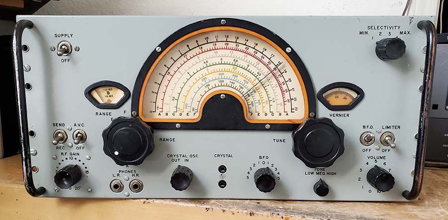
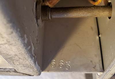
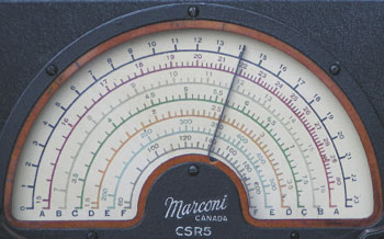
SN:665 is Back on the Bench -
Apr 21, 2026 -
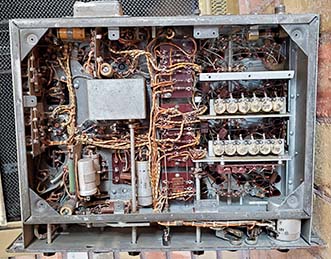
In checking over the CSR-5 SN:665, I performed a DCR test on all of the
resistors and all were easily within 20% of the marked value except for
R59. In looking
at the available Internet information, I can't really find a specific
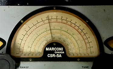
"parts list" for the CSR-5, only for the CSR-5A. I checked all of the
tag boards and the resistors all agree in value with the CSR-5A "parts
list." If this receiver was modified by the RNC to be a CSR-5A, then the
resistors are more-or-less correct. I can see that at least half of the resistors are
not original,...but they aren't brand new either. If their values have
been changed, it was done while the receiver was still in active use by
the RNC. The change from 6SK7 tubes for the 2nd RF amplifier and the 1st
IF amplifier to 6SG7 tubes that would operate at twice the gain would
seem to require an adjustment in cathode resistance and possibly screen
voltage. For V2, the 2nd RF amplifier, that would require some change in
either the 300 ohm cathode resistor or the 1000 ohm screen dropping
resistor, although these are CSR-5A values and the CSR-5 with a 6SK7
installed might have had different values. Definitely, R27, the cathode
resistor for V4 in the 1st IF amplifier is specified as "100 to 400
ohms" in the CSR-5A parts list, implying that it was a selected value
for CSR-5A receivers. However, SN:665 has what looks like the original
R27 installed and it's a 100 ohm resistor. Additionally, SN:577 also has
6SG7 tubes but a 100 ohm R27 resistor. Without a CSR-5 parts list
and, even if I found a CSR-5 schematic it wouldn't show component
values, I can only guess what value the resistors were
for V2 and V4 in a CSR-5 originally.
Out of curiosity, I replaced the two 6SG7 tubes
with NOS tested-good 6SK7. There wasn't too much difference in reception
except the AVC now seemed to work much better (remember, R27 is still
100 ohms.) I used WWV 15mc for a high
frequency strong signal and 4mc with an HP606B strong signal source for a low frequency. I
could definitely hear the difference when switching the AVC off and on.
When adjusting the RF gain, with the AVC on, at above 15 there isn't
anymore increase in sensitivity since the AVC has control at that level
on strong signals.
When tuning off of strong SW-BC stations, I can hear the AVC tc
delay as the AVC bias is reduced (goes less negative) and the RF/IF gain
increases, indicating that the AVC is functioning correctly with the
6SK7 tubes installed. I think the AVC problem is using 6SG7 tubes and then R27
being 100 ohms, there's too much IF gain and that overloads the AVC.
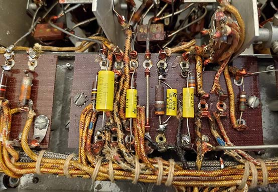
Comparing SN:394 to SN:665
- Since I can't find a CSR-5 "parts list" the next best thing is inspect
CSR-5 SN:394. After putting SN:394
on the bench and removing the bottom covers, it was unfortunately very
obvious that nothing could be determined from SN:394 because virtually
every resistor on the two IF tag boards, along with most of the
resistors in the receiver, have been replaced. The R-values
installed are what the CSR-5A parts list shows for the R-values and that
fits with the 6SG7 tube IDs and tubes. A comparison between the
two CSR-5(A) receivers follows:
In comparing SN:394 to SN:665,...SN:394 has R27 installed as a fairly
new style Allen-Bradley 470 ohm 5% resistor.
In SN:665, R27 is
the original 100 ohms (maybe original, measures 118
ohms - Cathode R for V4, 1st IF amplifier.)
I changed the 470 ohm resistor in SN:394 to 220 ohms. This resulted in
the receiver almost oscillating as SW-BC stations were tuned. I then
increased the R27 value to 390 ohms and that seemed to work better. In
SN:665, I changed R27 to 270 ohms and the receiver performed just about
the same as with the 100 ohms R27. I should change R27 to ~500 ohms
and put the 6SG7 tubes back in,...and I did, Apr 27th.
NOTE: Recent acquisition
CSR-5 SN:577 has the 6SG7 tubes with hand-written chassis IDs but R27 is
a 100 ohm resistor that appears original. Presently, this receiver is
non-functional. 5-4-26
Other
discrepancies are,...SN:394 has R34 (part of the Cathode divider for V5 2nd IF)
amplifier that measures 840 ohms (one of the few original
resistors but the color code damaged and can't be read with confidence
but appears that it was 500 ohms - green?, black, brown.)
I changed R34 to a 390 ohm resistor. No obvious change in performance.
In SN:665, R34 is an original resistor that measures 398 ohms (should be 400 ohms, so it's okay.)
In SN:665, R59 (the other Cathode divider resistor for V5)
is an original 400 ohm resistor that measures 602 ohms, a 50% drift so it should be
changed since it's somewhat affecting the cathode bias on V5.
I changed R59 to a 390 ohm resistor. No noticeable change in performance.
Cathode bias measured 2.1vdc and is shown as 2.5vdc in the manual
voltage check list.
In trying various resistors and gain control adjustments on SN:394, it seems the resistor that determines best performance is the value of
R27 acting something like an IF Gain control. If 6SG7 tubes are going to be employed, the value of R27 should be
hand-selected for best gain without overloading the AVC and without the
IF oscillating. The expected value would be between 100 ohms and 400
ohms and probably a lot closer to 400
ohms,...maybe even 500 ohms. I don't think the value of
R27 was that critical when using 6SK7 tubes but it should probably still be a value
of about 400 ohms. This higher value tends to keep the IF stage gain
reasonable and stable. An alignment of the IF also might prove
beneficial to stability and performance. NOTE:
CSR-5 manual is available on Jerry Proc's website. It indicates R27 is
either 400 ohms or 500 ohms where the CSR-5A manual indicates R27 value
is 100 ohms to 400 ohms. It seems likely that when CSR-5 receivers were
converted to CSR-5A, the original R27 was sometimes removed and the
minimum value specified was installed. This resulted in better CW
performance.
Shunting R61, the Re-radiation Resistor -
I've run SN:665 for about one month with the original R61 1000 ohm
re-radiation resistor installed. I didn't notice anything unusual but
when using the Johnson Matchbox to tune the Collinear Array, I seemed to
have trouble finding a "peak" response for the receiver. Finally, after thinking about the 1000 ohms in series with the
antenna input, it became mentally obvious that the input Z is a minimum
of 1000Z due to the series resistor. This might not be a problem if the
antenna used was an untuned end-fed wire where that type of antenna's
impedance is typically around 1500 ohms (maybe the inverted-L used on
some WWII ships?) But, most hams use their
transmitting antenna as the receiving antenna, therefore the antenna is
an unbalanced load with an impedance of 50Z to 75Z. The series 1000 ohm resistor was creating a
significant mismatch with my Collinear Array, a matched 50Z unbalanced
antenna. In the receiver I shunted the original 1000 ohm re-radiation
resistor with some 24 ga. TC and soldered the shunt in place. Now, the
receiver sensitivity is slightly improved (noticeable but not
over-whelming) BUT, the significant improvement is now the Matchbox does "peak" the
receiver response which indicates that the antenna Z and the receiver
input Z are a pretty close match. The other important note is that
the correct Matchbox setting for transmitter matching is also the same
setting for maximum response from the receiver at that frequency.
NOTE: On the Johnson
Matchbox, if the receiver is connected to the "Receiver" terminals on the rear
terminal strip on the Matchbox this will actually connect the receiver antenna
input to a slightly different tap on the primary coil of the Matchbox inductor. The idea
was to provide a 300Z tap for the receiver as opposed to the 50Z tap for the
transmitter. The typical antenna impedance for the receiver in the early 1950s
was 300Z. By 1960, most receivers were being produced with 50Z to 75Z antenna
input Z. I don't use this Matchbox connection and have the receiver
antenna input connected to the transmitter's antenna switching relay so the
receiver ends up connected to the lower Z tap on the primary of the inductor
providing about 75Z to 50Z.
Were the CSR-5A Changes to Benefit CW
Reception? - I think the 6SG7 tubes were used for
maximum sensitivity when operating in the CW mode, that is, with the AVC off, the BFO on and
riding the RF gain for best ratio of BFO injection to signal strength,...especially on Bands B and A.
It's also possible that, with CW being the primary mode of reception, the
Crystal Filter was used often and the additional RF/IF gain when using the
Crystal Filter may have been a significant help with
narrow bandwidth CW reception. Since this CW mode set-up
has the RF gain controlled manually with no AVC, the problems with
over-loading the AVC won't be encountered. For better AM-Voice operation with AVC controlling
the receiver sensitivity, I think the 6SG7 can be used if R27 has a
minimum value of 400 ohms,...500 ohms is better.
Certainly during WWII and for quite a long time afterwards, CW was the
primary mode of communications for the USN and probably for the RCN also. It seems logical that the
CSR-5A changes were to benefit the receiver's performance in that
primary mode of marine communication. The same sort of CW reception
design decisions
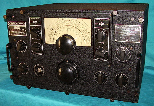
can be found in the WWII USN RAO-7 receivers where, certainly when used by
the USN, the RAO was never used with AVC and always was considered a CW
receiver to be operated without AVC. When using the RAO-7, it becomes
obvious that the AVC has way too much negative bias and when the receiver is
operated above 10mc in the AM mode, the AVC responds to the received noise
rather than the tuned signal with the AVC cutting back the sensitivity. This
only happens with the AVC on when searching for weak to moderate AM
signals. In the CW mode, with the AVC off,
reception is normal on all bands. The CSR-5A wouldn't be the only "Navy
Receiver" that was enhanced for CW reception to the detriment of AVC-controlled
gain for AM reception. It seems, that nowadays, the best
performance and operation for the CSR-5, many of which have been
"partially" converted to CSR-5A receivers, will depend on the individual's listening
preferences. For CW ops, 6SG7 tubes with the value of R27 at the lower
end of the range "100 to 400 ohms." For AM with AVC control,
6SG7 tubes with R27 value between 400 to 500 ohms.
Other Questions - Although R27
in SN:665 looked like the original resistor, there was a lot of
"non-original" soldering on the terminals and the cloth-insulated wire lead
condition and resistor lead wraps didn't look original. That's
unfortunate because, if it was definitely original, then one could
assume the the CSR-5 used 100 ohms for R27 and then later the CSR-5A
made R27 hand-select between 100 ohms and 400 ohms. I installed a 270
ohm resistor as a test and that value seems to work fine with 6SK7 tubes (I'm
contemplating changing this 270 ohm value to around 400-500 ohms for better
IF gain stability using 6SG7 tubes. I did this change Apr
27,2026 and the performance is much better with 6SG7 tubes for V2 and V4
and with R27's value at 500 ohms - Band A perked-up quite a bit.) So, I guess
the question would be, was R27 a 100 ohm resistor in the initial CSR-5
receiver? Apparently,...no. Original spec in CSR-5 parts list was
either a 400
ohm resistor or a 500 ohm resistor. Was R27 changed to "hand-select" between 100 to 400 ohms for
the CSR-5A with 6SG7 tubes? The answer is probably yes, some
receivers had 100 ohm resistors installed by the RCN for better CW
performance. Was a subsequent alignment of the IF section
part of the upgrade? As mentioned, SN:577 was found to also have an
original (well, vintage) 100 ohm R27
resistor.
The VOLUME control installed in SN:665 appears to be original. It
measures about 1.5 meg with the parts list value shown as 1 meg. With this
particular potentiometer, with a full CCW setting and the arm reads open to the grounded
terminal. A slight movement makes contact with the resistive element
with this initial resistance being about 25K to ground. The pot appears to be a
linear taper (okay for CW.) The listenable VOLUME level is between 0 and
1 with 2 being very loud. This is in the AM mode with
the AVC on, RF gain at 20 and tuned to a strong SW-BC station. CSR-5
SN:394 has had its VOLUME pot changed. The VOLUME adjustment on SN:394
works great with normal volume being achieved around 4 in the AM mode. I
don't like to deviate (if possible) from original components and
changing the original VOLUME control in SN:665 isn't going to happen. I'm sure there's nothing wrong
with the potentiometer and it's part of the original CSR-5 design. The
question here would be, do all original CSR-5 volume control pots
function in this manner of seemingly designed for CW operation where the
VOLUME would be set above 5 and the sensitivity controlled manually with
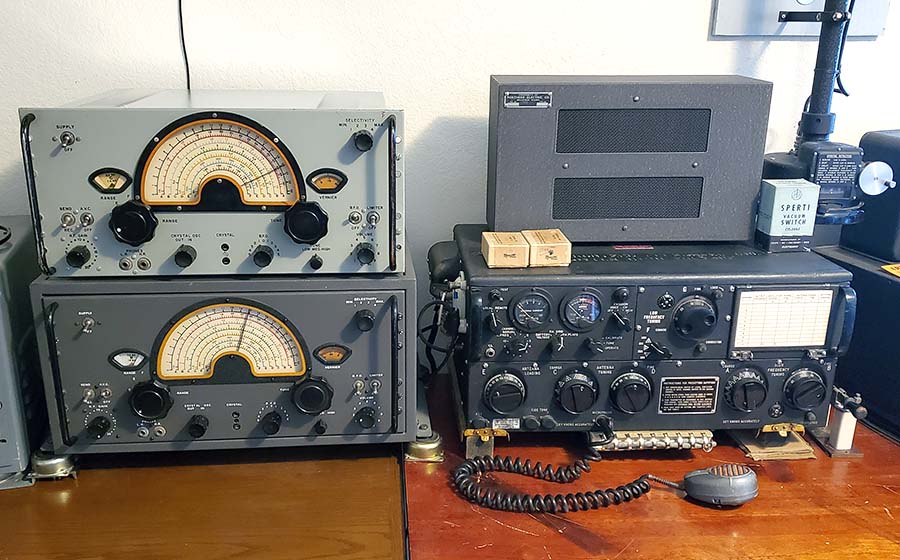
the RF gain? Of course, placing the loudspeaker on top of the receiver
and directly in front of the operator would have the perceived loudness
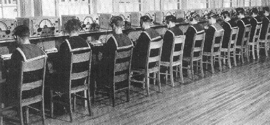
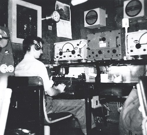
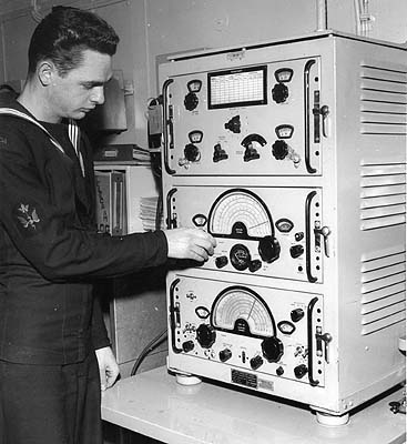
at maximum. The photo of the RCN ship Athabaskan radio room shows the
loudspeakers mounted high up on the bulkhead and away from the
operator's head. Also onboard ship, the ambient noise level would also
require more volume from the receiver - if the loudspeakers were used.
'Phones were the normal audio reproducers used onboard ship. Also, I'm
using the 10K audio output with the loudspeaker matching transformer
being an 8K to 8 ohm. I'd have to try the 500Z output and the 'phones
output for a valid comparison. UPDATE:
I tried using the 500Z output going to an LS-3 with a 600Z transformer
inside. The audio was just about the same as the 10K audio output going
to a matched loudspeaker.
It's obvious that the RCN changed several resistors over the period of
time that CSR-5 SN:665 was in active use. However, SN:665 is still
basically an "original" receiver since it was never "hamstered."
I did change the 6SG7 tubes back to 6SK7 tubes for a short time but after considering
that the receiver is going to be kept as original as possible, I've
returned the 6SG7 tubes (with an adjustment of R27 to 500 ohms for best
stability.) I wonder if any other owners of CSR-5 receivers actually have receivers that were
never "upgraded" and are still using original type 6SK7 tubes? In such a receiver
(if one exists,) I
wonder what the value of R27 would be? I'll bet it's 500 ohms.
|
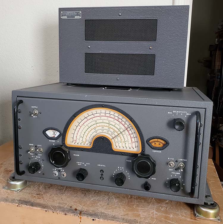
A Cabinet for
SN:665
UPDATE: May 12, 2026 -
I've installed SN:665 into the cabinet that was salvaged from CSR-5
SN:577. The cabinet was reconditioned and repainted using an
acrylic-wash technique. I used Barry mount
shock feet and instead of the side brackets, I've mounted the shock feet
similar to those shown in the vintage photo of the CSR-5A receivers on
the RCN ship HMCS Athabaskan (photo above in "Other RCN Mods.") This placement
of the shock feet reduces the cabinet width by 3" which is very helpful
when there's limited desk top space. The cabinet does have original
mounting holes for placing the shock feet in this position under
the cabinet. NOTE: I do realize that SN:665 was
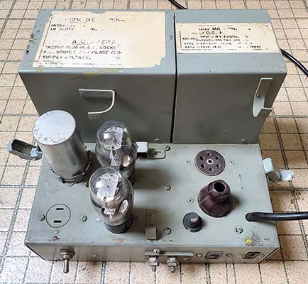
originally a rack mount receiver and part of a CM-11
transmitter-receiver. However, it's probable that during the
long careers that most CSR-5 receivers had with the RCN, some
rack mounts were later installed into cabinets if that was
necessary for the continued RCN-use of that particular receiver.
Matching the Paint Color
- It's a low probability of finding an exact color match from a spray can
off-the-shelf. However, after the cabinet is prepared, a color-wash can be applied
using an accurate color matched acrylic paint. That results in a matte finish
but it's the correct color. The gray color used on the panel of SN:665 used 12
parts white, 1 part black, 3 parts brown and 1 part green. Of course, these are
approximate to get close to the color and then the true color has to be matched
visually and usually adding more brown than expected. The matched and mixed Acrylic is thinned slightly with water and then "sponged"
on the cabinet in several thin applications that are allowed to dry between each
application. About three applications are usually required. The cabinet paint is then
allowed to dry for a few days before using. It's possible to "clear coat" the
acrylic paint for protection and to impart a semi-gloss look (although the
flaws would be even more apparent than they already are.) |
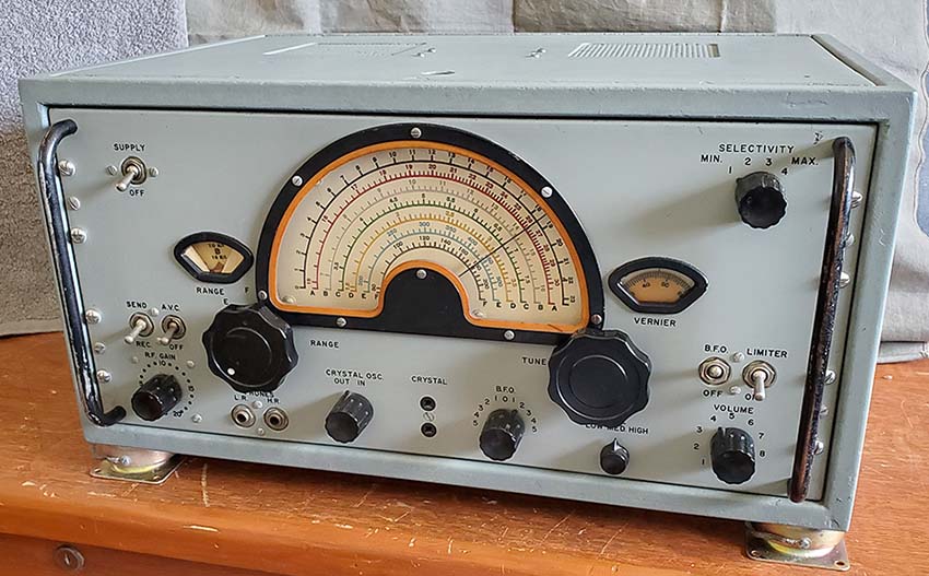
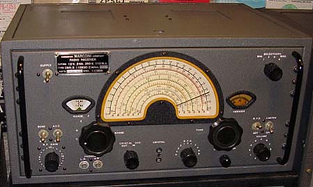
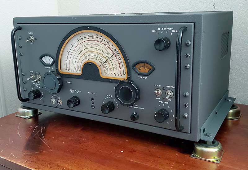
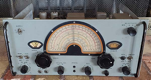
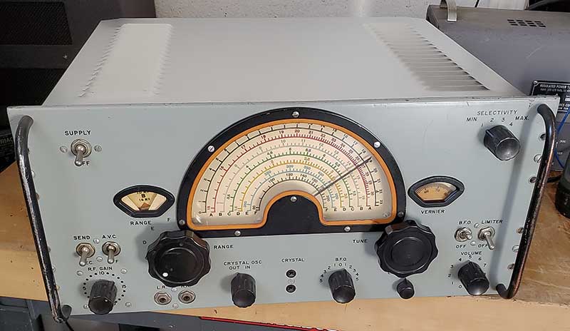
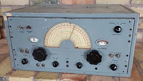
SN:665 installed in a CSR-5 table
cabinet - shock feet are Barry mounts |
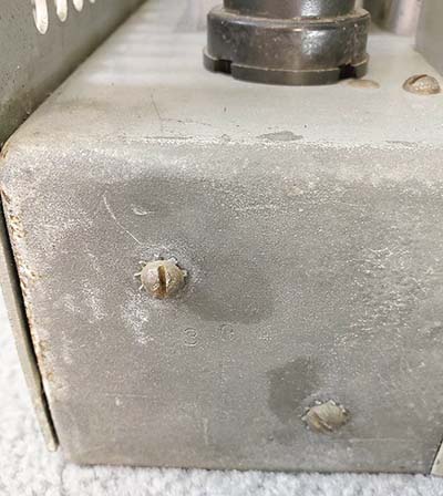
| Straightening the Cabinet
- The lid on this cabinet is very tight and virtually impossible to
raise just using the single finger hole. I took the cabinet
outside so I could wash out all of the debris that had collected
in the cabinet. I also wire brushed the rust areas. I heated the
cabinet using a hand-held heat-gun to drive out any water left
and then put the cabinet in full sun for a few hours to fully
dry the inside. Examining the "lid fit," it appeared that the lid lip was
at an outward angle that interfered with front of the opening. Ideally, the two
lid lip dimples should just touch the front of the opening and that provides a
positive-feel to the lid closure but lifting the lid with the finger-hole is
easy. I used a very close-fitting crescent wrench (set to the thickness of
the metal) to allow gentle bending of the lip. This has to be done carefully
to keep the edge straight as it's bent inward. This adjustment resulted in the
lid now being easy to lift using the finger-hole and still having a
positive-feel (because of the two dimples) to the closure.
Cabinet Prep and Paint -
I could see there were three coats of paint on the cabinet exterior. While I
could strip the paint, that's laborious work requiring multiple coatings
of methylene-chloride stripper all performed outside using special
gloves. If I was going to use automotive "custom-matched" spray paint, I would
have to go that route. The automotive matched-paint is the best
way to achieve a durable coating but, being a smooth finish
paint, the cabinet prep has to be perfect or any blemishes under
the paint will show through. Using the acrylic wash is much faster and
a lot easier. I just used a hand-held sander and went over all of the cabinet to try
to "level" the paint surface and remove as much rust as possible. Interestingly,
it appears that the cabinet was initially painted silver. This was probably a
primer or a rust preventative type of paint, like cold-galvanizing paint. It
appears that the interior wasn't painted after the silver primer. Only the
exterior of the cabinet was painted the particular color that was required by the RCN and for the installation. In the case of this cabinet, the original color
looks like a pale greenish-gray color. Sometime later (maybe much later,)
this greenish-gray was given a coat of red-oxide primer and then
the cabinet was sprayed with a heavy coat of machine gray paint.
Since the red-oxide prep probably required sanding, if the
greenish-gray had been a wrinkle finish, that can't be
determined now. Three coats of acrylic wash were required,
allowing several hours of drying time between the coats. The
color match is very close as can be seen in the photo above. Now, this
acrylic wash painting process isn't perfect but it's a
quick and easy way to get a near-perfect match on the color needed. As
mentioned, the acrylic finish is matte and, even with a sanding prep, many of the cabinet flaws are still
visible (imparts a vintage look,...maybe.) These flaws are almost
invisible when the receiver is installed in the station with the
ART-13A transmitter and ambient room lighting is present.
|
|