Radio
Boulevard COLLINS RADIO
COMPANY KWS-1 - 1000
watt SSB, CW, AM, AFSK Amateur Transmitter 75A-4 - SSB, CW, AM Amateur Communications Receiver
|
|
This write-up contains just a little bit of history about the KWS-1 and 75A-4 and no history about Collins Radio Company. Most of this article's written material relates my own experiences with KWS-1 SN:616 and 75A-4 SN:850. I've owned this Collins pair since 1970. A second 75A-4, SN:4470, was added in the 1990s (one of those "lucky finds.") I've included brief circuit descriptions of my equipment but, for the official "Collins-written" descriptions of the equipment along with more Collins manufacturing history, go to the Collins Collector's Association website. This write-up is more about the problems I've experienced and what I've had to do to my KWS-1 SN:616 and 75A-4 SN:850 to keep them running, albeit not continuously, for over half of a century. |
Collins Radio Company - KWS-1 Transmitter and 75A-4 Receiver Collins Radio Company designed much of their radio amateur equipment based on their commercial broadcast equipment and especially on their military contract equipment. The design of a powerful Single Side-Band Suppressed Carrier transmitter capable of 1000 watt PEP input power was part of Collins' development of SSB communications equipment for the military. In 1956, Art Collins along with Major General Francis "Butch" Griswold flew halfway around the world twice with airborne SSB equipment consisting of the Collins KWS-1 transmitter and two Collins 75A-4 receivers, staying in communications with Offutt AFB in Omaha, Nebraska and promoting the advantages that SSB comms had for reliable HF long distance voice transmissions. Also, to further show the advantages of SSB Voice Communications, they engaged in QSOs with amateur radio operators around the world during the flights. The KWS-1 and 75A-4 were used by several MARS stations and were often heard transmitting signals from military and research stations in Antarctica. Any KWS-1 and 75A-4 are an integral part of this heritage and any actual inspection of the transmitter or the receiver construction reveals that they were built to military specifications. The partnership of the KWS-1 and 75A-4 into a late-1950s ham station certainly represented "the ultimate" in modern performance. Today, the KWS-1 and 75A-4 are highly respected for their quality of construction and level of performance. And, even though they are fast approaching the three-quarters of a century mark since their design inception, both are still easily capable of, and compatible with, modern amateur voice communications. |
|
The KWS-1 - was an incredible transmitter when it was introduced in 1955. At a time when AM dominated the voice mode of communications, Collins introduced a high-power SSB transmitter that was built to military specifications and had the most modern (at the time) method of carrier suppression (a balanced ring modulator) and a dual crystal-controlled carrier oscillator for shifting upper or lower sideband frequencies with a Collins mechanical filter for suppression of the unwanted sideband. The transmitter used a Collins PTO and crystal controlled oscillators in combination with mixer stages for a coverage of 80M through 10M (1mc wide bands that covered the HF amateur bands,) for dial accuracy to the kilocycle and to virtually eliminate frequency drift. The power amplifier was linear Class AB1 and used a pair of force-air cooled, external anode final amplifier tubes, 4X150 types. A separate power supply unit had electronic voltage regulation for PA screen voltages (other voltage regulation was in the desk top transmitter unit) and a squirrel-cage blower supplied the air flow necessary to cool the finals. Due to its military-type construction the KWS-1 was expensive,... so expensive, only a genuine enthusiast would pay the expected high price of $2095. Judging by the number of KWS-1 survivors, there were actually quite a few ham enthusiasts that purchased KWS-1 transmitters. However many KWS-1 transmitters were also purchased by the military with some of those going to MARS use and also a few commercial users, so the actual number of ham-owners is not really known. Production of the KWS-1 ran from 1955 up to 1958. It's generally thought that about 1600 units built and sold during that time. The 75A-4 - was introduced in 1955 and manufactured up to about 1958 or so, with around 6000 receivers for total production. The initial selling price started around $500 and continued to escalate to $695 at the end of production in 1958. The 22 tube circuit featured a 3.1 kc mechanical filter and a product detector, making the 75A-4 ready for SSB - but it could also copy AM quite well since a separate AM envelope detector was also provided. >>> |
>>> For better AM copy an optional 6.0 kc mechanical filter could be purchased or, for CW,
an 800Hz filter was available. Later, other filter frequencies were
offered, e.g., 500 cycle for CW, 2.1 kc for SSB, 1.5kc for RTTY, plus others. Up to
three mechanical filters could be installed, providing optimum
selectivity for CW, SSB, RTTY or AM. Frequency readout was "Collins accurate"
and sensitivity was competitive. The USAF SSB Test Using the KWS-1 and 75A-4 - The ham enthusiasts certainly had been following the well-publicized "test flights" that involved Art Collins and USAF General Francis "Butch" Griswold along with General Curtis LeMay and the USAF. The "SSB Tests" were two flights of a C97 "Stratofreighter" airplane that was equipped with the KWS-1 and two 75A-4 receivers to prove that reliable HF-Voice communication from half-way around the world to Offutt AFB in Omaha, Nebraska was possible using SSB. The first test flight was from Offutt AFB out to Okinawa and back from March 25 through April 3, 1956. SAC wanted another test that involved the polar regions that were where SAC typically operated and that area was noted for difficult radio propagation. The second "test flight" went to the polar regions above Greenland and back to Offett AFB on June 29 through July 7, 1956. Radio amateurs were also part of the communications for both flights with contacts made being logged and QSLs sent to confirm the contact (see QSL card to the right.) The radio equipment was essentially a stock KWS-1 with the exception of the aircraft-type shock mounts and that the KWS-1 blower motor had to be changed to operate on the 400~ AC. The equipment table had the 75A-4 on the left and the KWS-1 on the right. The KWS-1 power supply was behind the left side of the desk and behind the 75A-4. A second 75A-4 was placed on top of the KWS-1 power supply facing out toward the center of the fuselage. A 270G-3 loudspeaker was on top of the desk-mounted 75A-4 (that also was on an aircraft shock-mount.) There was a Collins 180S-1 antenna coupler used to match the aircraft wire antennas although it's not seen in the photographs since it was mounted on the fuselage wall where the wire antenna exited. There was another piece of equipment to the right of the KWS-1 that appeared to be a station control for switching antennas and other operational functioning. The photos show an Electro-Voice 664 microphone being used and that implies that the VOX was used to control the T-R function. Although testing SSB communications was the primary purpose, note that a "bug" is to the right of the EV-664 mike (maybe for CW but probably for "tuning up" the KWS-1.) |
|
With the success of these SSB tests, Collins went on to design SSB radio equipment that was specifically for airborne operations, that is, to run on 400~AC and to be constructed in a weight-saving package. It was impressive that almost stock Collins equipment could be fitted into an aircraft and operated effectively. Everything about the KWS-1 had to be military first-class. And, the construction of the KWS-1 WAS military-grade with first-rate components and a design that was "cutting edge" for 1955. Any detailed physical examination of a KWS-1 transmitter will make it apparent that no expense was spared in construction and the eventual selling price really wasn't a consideration but performance and reliability were. The 75A-4 was the ultimate evolution of the 75A Series of Collins receivers. There were a lot of influences from the Collins military receivers, such as mechanical filters used for selectivity. Many improvements were for SSB reception, such as separate detectors, a product detector for CW/SSB and a diode detector for AM. The unique Passband Tuning control and the T-filter/Q-multiplier Rejection Tuning allowed the user to reliably copy stations despite heavy QRM. The build-quality was military and, like the KWS-1, any detailed inspection of a 75A-4 will certainly show the quality matched the KWS-1. |
KWS-1 Details It's difficult for me to believe that I've owned KWS-1 sn:616 for over half-a-century. What's maybe more surprising is that the transmitter is still functioning great and still looks incredibly nice. And, it wasn't even new when I bought it back in 1970 with the transmitter being 15 years old at that time (and there were two other owners before me.) There aren't many types of electronic equipment from the mid-1950s time period that can still be successfully operated in a modern mode of communication after all that time. Single Side Band-Suppressed Carrier is still the most popular mode of voice communications on the HF ham bands. So the KWS-1, while not the earliest of SSB rigs, is certainly one of the best designed, best built and certainly has the greatest longevity of usefulness of any of the mid-1950s ham transmitters. |
|
The KWS-1 Circuit - The KWS-1 is capable of 1KW PEP input power SSB transmission utilizing a 3.1kc mechanical filter and balanced diode-ring modulator to create the selectable USB or LSB signal with suppressed carrier. Two crystals, one 1.5kc above and the other 1.5kc below 250kc allow the Crystal Oscillator to provide the correct frequency offset for either upper or lower sideband. The diode ring balanced modulator eliminates the carrier and then the signal is routed through the mechanical filter to remove the undesired sideband by shifting the signal frequency to either 251.5kc or 248.5kc where the selectivity of the MF only allows the selected sideband modulated information waveform through. Further mixing and amplification in various stages converts the SSB signal to the proper output frequency with the driver output stage being a pair of parallel 6CL6 tubes capable of three watts of power. The output of the drivers is then routed into the Class AB-1 Linear Amplifier comprised of two 4X150 external anode, air-cooled tubes operated in parallel (nowadays 4CX250Bs.) Plate voltage is 2KV. Fully loaded PA plate current is 500mA resulting in the power input of 1000 watts. The power output "key-down" of a properly operating KWS-1 is around 600W. In the AM mode, the carrier is reinserted but the signal is still kept in a single-side band mode. Operating a KWS-1 in the AM mode will usually foment some negative comments from the "BC-Audio Crowd" but, unless mentioned, many "more tolerant AMers" (those without a panadapter, at least) never notice that only one sideband is being transmitted. Since AM is a 100% duty-cycle mode, the output power has to be reduced (using the CARRIER LEVEL control) to about 150W of carrier output. In the CW mode a full 1KW (input power) can be utilized since the CW duty-cycle is usually around 50%. For FSK-RTTY, again since this is a 100% duty-cycle mode, the output power must be reduced to 150W. FSK mode is actually SSB with an AFSK signal of two audio frequency sine wave tones running to the audio input (either the 600Z phone patch input or the Hi-Z MIC input) of the KWS-1 which will result in a FSK RF output since the carrier is suppressed and only one sideband utilized. The separation of the two audio tones defines the frequency shift with the most common shift being 170hz. Due to the 3.1kc mechanical filter, the KWS-1 sounds incredible on SSB today since most hams are used to hearing rather narrow SSB (2.1kc) and generally a QSO using a properly adjusted and correctly operating KWS-1 will garner many positive comments regarding its "wider than normal" SSB audio. The KWS-1 power supply is contained in the larger floor mount pedestal. Originally, a pair of 866A HgV tubes were used as rectifiers but those troublesome tubes normally will have been replaced with "trouble-free" 3B28 HV rectifiers or some users even go SS rectifiers (I use 3B28s.) The regulated screen voltage is adjustable and so is the plate voltage to a certain extent (you can move the connections to different taps on the plate transformer.) Later versions of the KWS-1 added louvers to the front panel of the power supply (I suppose some of these do exist, I've only seen the louvers in advertising photos from 1958, as shown to the left.) The squirrel-cage blower is also mounted in the base of the pedestal. It's fairly noisy (bearings should be lubed every few years and many just need to be replaced) and the air output is routed through a very long, 2" diameter, radiator hose (the long hose was provided so that the transmitter could be placed on the operations table, although almost all advertising shows the transmitter on top of the power supply - recessed dimples for the rubber feet of the transmitter bottom to set in provides for a secure placement on top of the power supply.) The +2KV plate voltage is run through a cable made from RG-58U and the HV connector on the RF unit can be somewhat problematic in its ability to stay connected (many have been replaced with a more stout connector over the years.) The remaining power is routed through a flexible cable with a rectangular Amphenol multi-pin connector. The auxiliary outputs and inputs are routed to a second rectangular Amphenol multi-pin connector. Both Amphenols are secured to the transmitter with screw-clamps when plugged in. The weight of the power supply pedestal is 180 lbs. and the desk transmitter weighs 50 lbs. |
Where KWS-1 sn:616 Came
From - I purchased my KWS-1 sn:616 from Al Burnham, K6RIM, in
December, 1970 (I was 20 years old then.) I had upgraded to General in August 1970 and had been
using a really crummy Hallicrafters HT-37 transmitter (a phasing SSB rig.) The owner of
the Burlingame HRO (Mr. Silverton) told me he knew of a KWS-1 that might
be for sale soon. I managed to get the owner's phone number from
Silverton a couple of weeks later. A phone call to K6RIM got the
appointment set up. Al B. was also located in Burlingame, so it was an
hour drive to his QTH where got a quick demo and the sale was
made,...$600 (I picked the transmitter up in my 1948 Willys
Station Wagon [2WD with over-drive] that I had back then. Al helped to
load the KWS-1 power supply into the back of the Willys.) Al had purchased KWS-1 sn:616 in used condition, in 1960, from Amrad
Electronics in Burlingame, California (later, Amrad Electronics became Ham Radio Outlet in
Burlingame.)
K6RIM is still very active DXing on HF (and he does know that I still
own sn:616 and that it's here in Dayton Valley, Nevada.) More Recent History - SN 616 was my main transmitter for many years and has proven to be a super-flexible unit capable of high power SSB and CW with reduced power AM and RTTY communications. I ran RTTY with the KWS-1 from 1974 up to 1980 out of Gardnerville, Nevada. There was a 10-year time period from 1980 up to around 1990 when the KWS-1 was in storage inside a large, well-insulated pump house on our Minden, Nevada property back then. It managed to survive this neglect without any issues since the pump house was very dry and well-insulated (it never got below freezing and never got any warmer than about 80ºF - and it was dark, unless I opened the door - or left the light on for heat during the winter.) In fact, the KWS-1 has only had routine maintenance performed on it over the years (meaning the KWS-1 is mostly all original.) The Service Bulletin changes and other Collins ECO-type changes that have been incorporated are removal of the fiberglass insulation from inside the PA box, installation of Collins heat-reducing tube shields, replace 866A tubes with 3B28 tubes, replace 4X150 tubes with 4CX250B tubes and I added a rubber isolation mount for the auxiliary relay inside the KWS-1 chassis. I did have to repair a broken flex connection on one of the roller inductors several years ago, also a broken wire in the microphone connector. In 2007, I set up the KWS-1 and 75A-4 to run RTTY using a Model 19ASR machine I had owned since 1974. I had everything set up in the basement in Virginia City, Nevada and the station ran great but I only contacted a few "real machine" RTTY enthusiasts. I did another set up in Dayton Valley in 2021 using the KWS-1 and 75A-4 to run "real machine" RTTY. I used my homebrew TU and got good RTTY copy but the transmitting end of things didn't go so well. I was using my Model 28 Compact (an ultra-small, desk-top Model 28) that works very well. The problem was the KWS-1 was f-drifting too much for modern transceivers (or maybe it's too much f-drift for modern RTTY operators,...but more on that further down.) I now occasionally use the KWS-1 on AM on the Vintage Military Radio Net where it provides a unique type of AM for enthusiasts to hear - one selectable sideband with carrier. The KWS-1 transmitters have a long association with military MARS stations, especially with the 1957 Geophysical Year and the MARS operators out of Antarctica. The KWS-1 is certainly one of the best from the "Golden Age of Ham Radio." |
|
KWS-1 OPERATIONAL NOTES |
|
SSB - The KWS-1 is flawless in producing a very powerful,
great sounding SSB signal. The use of the ALC control works something like
an audio compressor (although it's fed back from the PA circuit,...maybe more like AVC) in that it will limit the higher voice peaks to allow more audio
from the average voice dynamics. This results in higher average power
output. Adjust the ALC for no PA grid current to show while talking into
the microphone. To run less power output, the AUDIO GAIN can be turned
down and readjust the ALC control. The KWS-1 also has VOX operation
along with PTT options.
CW - Operation in the CW mode is also quite easy with the KWS-1. Power output can be controlled by using the CARRIER LEVEL control. The audio and VOX circuits are disconnected in CW. There are a couple of wave shaping filters also. I operated a lot of CW DX with the KWS-1 and always had good reports,...at 1KW input on CW, the signal is dominating! AM - When operating on AM there are a few things to remember,...the KWS-1 will NEVER sound like double-sideband AM and it will NEVER sound like high fidelity AM. No matter how many times you describe the KWS-1's method of generating an AM signal and the fact that it's a "single sideband signal with reinserted carrier" you'll still run into those listeners that expect AM BC Collins 20V-quality audio from anything built by Collins. However, a few things performed during AM set-up can avoid most "Critical Audio Reports" when using the KWS-1. Be sure to run the carrier reinsertion (Carrier Level) so that it results in about one-quarter unmodulated output power as compared to full power output. This is usually about 150 watts of carrier power and is usually achieved at about 250mA of PA current. >>> |
>>> Typical full power output DC on a KWS-1 will be
around 600 watts so one-quarter would be around 150 watts. Be
sure to run the Audio Gain very low - usually about 1 or so -
and NEVER use the ALC - always keep the
ALC at full CCW in the AM mode. Be sure to monitor the PA Grid current -
it should never move from 0. Any grid current flowing will indicate
distortion. Even a minor fluctuation of the Grid Current meter needle is
indicating non-linearity and resulting distortion. Use an
oscilloscope to monitor your modulation but also watch
the Grid Current constantly. Following these suggestions will have
your KWS-1 producing "its type of AM" about as well as it can. You'll
still might get "Critical Audio Reports" and sometimes you'll just have to
tell the "reporter" that the KWS-1 wasn't designed as a high-level
plate-modulated AM transmitter. It wasn't designed as an AM broadcast
transmitter. It's a high-power SSB transmitter that
can do AM in a method that produces "communications quality" audio with
a narrow bandwidth (single sideband with reinserted carrier) and THAT was what was important for hams (and some military users) in
the 1950s. RTTY - Operating RTTY was very easy only requiring a Audio Frequency Shift Keying Oscillator that operated from the TTY keyboard output to provide the Mark and the Space coding with the AFSK oscillator providing two audio sine wave tones for Mark or Space separated by the desired shift. 850Hz was the military standard in the early fifties but hams were moving to a much narrower shift of 170Hz, which has been the standard shift used since the 1970s. The AFSK oscillator output was connected to the MIC Input on the KWS-1 or to the 600Z phone patch input (depended on the type of AFSK oscillator circuit used) and the mode switched to SSB. Since RTTY is a 100% duty-cycle mode, the power output of the KWS-1 had to be set to 25% of full output or 150 watts output power. The power output of the KWS-1 could be set using either the AUDIO GAIN or by the output level on the AFSK oscillator. Since the transmitter was suppressed-carrier and single-side band, the two Mark or Space tones appear to be two RF signals separated by the 170Hz shift. Double Check PA TUNING on AM or RTTY - Collins really thought that nobody was going to operate AM at one-quarter power when they could operate full-power CW or SSB. So, their AM set-up is sort of "try and see" how it will work. Basically, Collins has you set-up for CW at full power, matched to the antenna, with the Carrier Level producing about mid-scale grid current and PA current at 500mA. Then switch to AM and reduce the Carrier Level to show 250mA PA current and set the Audio Gain as required. The problem is how the antenna load-matching reacts to different carrier wave envelopes that are produced at about 600 watts output and 150 watts output. >>> |
|
>>> If you run the KWS-1 into a dummy load and do the Collins set-up, there's no difference in full power or one quarter power as far as the position of the TUNING and LOAD controls. When running into an antenna system that has some reactance then there might be a slight difference. What I do is to follow the Collins set-up to the point where I've reduced the Carrier Level for 250ma of PA current, I then check the PA TUNING for the correct "dip" (making sure the SWR is still 1:1.) Most of the time, with a perfectly matched antenna, there's no difference but experimentation will determine if your KWS-1 on AM with your antenna will react the same way. If there's some reactance that can't be removed with the antenna matching device, then use the PA TUNING to dip the PA current, then adjust CARRIER LEVEL for 250ma of PA Current (and that should equal about 150 watts output power measured on an external RF watt meter.) Frequency Drift - More complaints are to be expected when using modes other than AM. Especially nowadays when the majority of hams are using modern transceivers and expect absolutely zero drift. The stock KWS-1 will f-drift a little,...very little,...usually <500hz during a hour-long QSO. In the 1950s through the early 1970s, the slight <.5kc drift was not considered a problem because every ham used separate receiver-transmitter setups and a slight retuning of the receiver was normal operating procedure. Besides, the KWS-1's <.5kc drift was so much better than most other rigs at the time. But, today any frequency drift is unacceptable and you're likely to receive a "critical frequency stability" report when operating some modes. Some KWS-1 users will employ a synthesizer as an external VFO (input to the BNC "EXT. VFO") or use a DSO (digitally synthesized oscillator) device to keep the KWS-1 at "zero drift." The only mode where the "stock f-drift" isn't even noticed is on AM. SSB might garner a few minor complaints (doubtful) and CW QSOs are so short with very short exchanges that the KWS-1 doesn't have much time to drift. Unfortunately, RTTY using a stock KWS-1 is impossible anymore (without using an external DSO.) RTTY and f-Drift - Operating RTTY using the KWS-1 using an AFSK oscillator into a SSB transmitter really made "real machine" RTTY easy! From 1974 up to 1980, I ran KWS-1 SN:616 at reduced power doing "real machine" RTTY with a Model 19ASR machine with no problems. I also ran "real machine" RTTY with the KWS-1 out of my Virginia City basement ham shack in 2007. Not anymore! An attempt at "real machine" RTTY in 2021 (from Dayton Valley, Nevada) was a disaster because of the "zero drift" necessity when communicating with modern transceivers that have a built-in RTTY mode interfaced with a computer for the Baudot code. Nowadays, when operating RTTY, a drift of 10 or 20 hertz will put your FSK signal out of the TU (Terminal Unit - the RTTY demodulator and keyer) filter's bandwidth, so very little drift will be tolerated in the RTTY mode anymore since modern RTTY operators refuse to actually tune their receivers (or use the RIT on transceivers. They also refuse to use Carriage Return or Line Feed since they're on a computer, not a "real machine.") Back in the 1970s, I used to have to keep retuning the receiver during a RTTY QSO due to the transmitter drift on the other end. This was NORMAL,...then. That was why ALL of the RTTY TUs back then had keying indicators for Mark and Space or oscilloscope displays,...so you could visually see that the proper Mark and Space keying was happening. The military's elaborate CV-116 Diversity RTTY TU had a built-in motorized-tuner that worked off of the incoming signal and kept the received RTTY signal always "in tune" since f-drift was expected. Many older RTTY TUs were more forgiving and some military TUs worked on just one audio frequency bandwidth and any deviation above or below the "center frequency" was part of the Baudot code being sent, so drift wasn't too much of an issue (the USN CV-89A TU worked that way.) Not so today when actually finding a RTTY signal that's being produced by a "real machine" is unheard of and all RTTY signals heard are computer generated Baudot converted to FSK by a modern transceiver's circuitry. |
|
|
Possible f-Drift Solutions (but remembering that the KWS-1 f-drift is only <.5kc per hour) - Some neurotic KWS-1 owner-users believe that excessive heat from the PA box being so near the PTO is the cause of the f-drift. Their modifications included fans or adding more fiberglass insulation on the exterior of the PA box near the PTO (there is some fiberglass insulation on the PA box exterior on the side nearest the front end of the transmitter but I think all of the fiberglass used inside and outside of the PA box was for sound proofing not for heat.) What I've found is that the small PTT auxiliary function relay is directly mounted on the same aluminum bracket that's used as part of the PTO mounting. The vibration of the relay "clicking" on and off with the T-R function will cause a very slight "bump" each time in the PTO frequency (just a few hz.) That "bump" seems to add up over the duration of a QSO but it's still <.5kc per hour. I noticed this when operating RTTY in the mid-1970s (my RTTY signal was actually received "over the air" through the TU to provide TTY printer copy so any drift in the KWS-1 was instantly apparent - the keyboard and the printer were on separate lines so I didn't use "local" copy.) Careful experimentation showed that the PTO frequency change only happened on the transmit or receive actuation of the auxiliary relay and there really wasn't any drift otherwise. My solution was to add some rubber cushions to the mounting of the relay and that seemed to cure the problem. However, that was fifty years ago (1975.) The 2025 bottom cover-off examination revealed that the rubber I used is holding up just fine and it's still very flexible. Another problem that could be encountered would be with the PTO. The ferrite cores used in all Collins PTOs sometimes have aging problems since most of the seals (for maintaining a vacuum) on the PTO have probably deteriorated over the past 70 years allowing air and moisture to ingress and that seems to sometimes have detrimental effects on the ferrite (although it takes quite a long time,...but, it's the reason Collins wanted all PTOs to be returned to them for repair and calibration since their final step was to seal the PTO to maintain the vacuum. Also, some PTOs were pressurized with nitrogen, the R-390A PTOs, for example.)The BEST and EASIEST solution to the
drift problem (IF it really is a problem for you) is the use of an external
modern synthesizer device connected to the EXT. VFO input. It's
easy and it's non-invasive. Or, just operate in the AM mode
where frequency drift isn't an issue. More RTTY? - The 2021 photo to the left shows the RTTY set up for "Real Machine RTTY" with a Teletype Corp. Model 28 Compact. Someone thought the Model 28 Compact would look nice painted turquoise (and it does look kinda cool) but the original Teletype Corp. color was boring machine-gray. The 1977 TU is the small box below the Model 28 Compact and it's my own "homebrew design and build," all solid-state unit that I used extensively from 1977-1980. This set up was for a 2021 "real machine RTTY" experiment that worked great for receive but transmitting turned into a disaster due to the "Interesting Problem" covered in the next section down. However, since the KWS-1 problems have been sorted out, it's possible that I might give "Real Machine RTTY" another try. I now have an excellent HAL ST-6000 TU and the Model 28 Compact is ready to go,...so who knows? |
An Interesting KWS-1 Problem for 2025 I decided to once again service the KWS-1 and put it back on the air. Last use was the 2021 RTTY debacle and the KWS-1 has sat in the corner of the ham shack since then. So, I moved it out to where I could have easy access to the entire transmitter. All cables and connections were set up. The KWS-1 was powered-up and allowed to warm-up for a while. A quick test into a dummy load and everything worked fine. I decided to test all of the tubes since it has probably been over 20 years since that was done. I did replace the 6CL6 driver tubes a few years ago but that's all. There are over 30 tubes in the KWS-1. The 4CX250B tubes can't be tested directly and neither can the 3B28 tubes. All others can be tested in the TV-7B tube tester. All tubes tested good. None were marginal. The only questionable tube was the 2D21, a thyratron that showed a short (high leakage) on the cathode. The tube actually conducts unless the bias goes high enough, then the tube doesn't conduct. The 2D21 tested just fine. It's function in the KWS-1 is a PA Screen protection circuit. I think it's actually okay and just the TV-7 test information isn't entirely complete. Once again, the KWS-1 was operated into the dummy load. The band was 80M. The modes checked were CW with no problems. SSB tested with no problems (monitored on RACAL RA-17L receiver.) I tested AM with no problems. I used an oscilloscope connected to the dummy load for monitoring the waveforms and in each mode they appeared normal. So,...perfect operation into a dummy load. However, when connected to the Collinear Array antenna system that provides a 1:1 SWR match, the KWS-1 appears to oscillate when in AM or SSB. This might be a neutralization problem and, since I did replace the 6CL6 tubes a while back and didn't neutralize then, I'll have to go through the neutralization procedure now. Why the KWS-1 doesn't oscillate on the dummy load and does oscillate with the antenna load is what's causing the confusion (and soon I was to discover that the problem was ONLY on 80M.) I replaced the National brand (rebuilt or repackaged tubes) 6CL6 tubes even though they tested good. I had a pair of RCA-JAN 6CL6 tubes that were NOS (and tested like NOS.) These RCA-JAN tubes were installed for the drivers. Next was to test the other bands. |
|
Dummy Load versus Antenna Load Test 15M Test - Full power into 50 ohm dummy load,...CW no problems, AM no problems (25% of full power) and SSB no problems, connected to the antenna, all modes, full power - no problems 20M Test - Full power into 50 ohm dummy load,...CW no problems, AM no problems (25% of full power) and SSB no problems, connected to the antenna, all modes, full power - no problems 40M Test - Full power into 50 ohm dummy load,...CW no problems, AM no problems (25% of full power) and SSB no problems, connected to the antenna, all modes, full power - no problems 80M Test - Full power into 50 ohm dummy load,...CW no problems, AM no problems (25% of full power) and SSB no problems. BUT connected to the antenna,...CW seemed okay, AM and SSB produces oscillation in the mixer stage and 6CL6 drivers. Since the 250kc oscillator is reinserted behind the MF, it would be difficult to distinguish the problem oscillation from normal CW operation. In AM, this reinserted carrier is adjusted for 150 watts output and with the oscillation, the CARRIER can't be adjusted to "zero" or 100mA idle PA I to start. Of course, I should go to CW and adjust the CARRIER LEVEL to zero and see what happens. Unfortunately, I only have the Collinear Array antenna available for the upstairs shack. A second antenna that used a coaxial cable type of feed-line, if it was available, would provide an interesting comparison. The KWS-1 has a dedicated, switched into the circuit, 80M neutralizing set up. The first thing to try is adjusting the 80M neutralization (this is where I went "off the track" for a while and seemed to forget that the KWS-1 worked fine into a dummy load on all bands.) 80M Neutralization - There are two adjustments involved in the 80M neutralizing. One is the 6CL6 80M plate tuning and the other is the 80M neutralizing trimmer. The equipment was set up for neutralizing and the adjustments were made. It was discovered that while the 6CL6 80M plate tuning would resonate and could be easily adjusted, the 80M neutralizing trimmer had no effect on anything. At this point, it looks like the problem is in the neutralizing trimmer and how it connects into the circuit through the band switch. I removed the bottom of the KWS-1 to inspect this area of the transmitter. Nothing was found. I used a DMM to check that the switch made the proper connections when 80M was selected. Unfortunately, the switch segment that is used for 80M is right up against one of the compartment walls and it's next to impossible to really see the contacts, even with a small dental mirror. I cleaned the band switch with DeOxit and a small paint brush just as a precaution. 
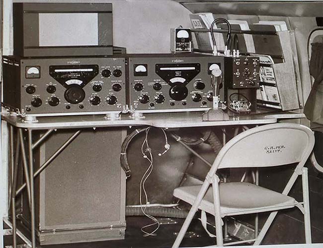
TEST 80M Neutralization - 
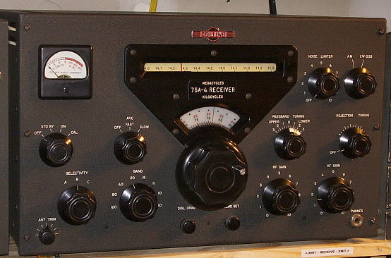
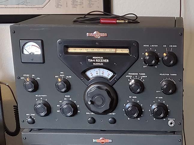
The KWS-1 manual's 80M neutralizing procedure has you connect a receiver with S-meter to the 6CL6 output and then monitor the 
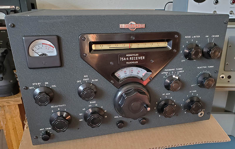
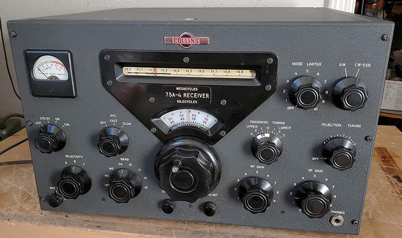
S-meter reading for an indication of neutralization. I was using the 75A-4 and to have the S-meter function, the RF gain has to be advanced and the AVC has to turned on. To have this actually be sensitive enough to show ANYTHING requires someway to vary the coupling between the KWS-1/6CL6 output and the 75A-4 input. It all seems rather crude and it's described that way because in 1955, most hams didn't have access to high-quality oscilloscopes. Next time, rather than use the crude hook-up described in the manual, I'm going use an oscilloscope to actually "see" what is happening as the 80M Neutralizing trimmer is adjusted. Hopefully, some sort of change might be seen when adjusting the 80M neutralization. It's NOT the 80M Neutralization - RFI? Grounds? Counterpoise? - Using the oscilloscope made finding the neutralization adjustment on 80M pretty easy. However, it doesn't change the fact that the KWS-1 on 80M going into a dummy load operates just fine. No problems at all! I even listened to the signal (leakage from the dummy load) on the GPR-90 receiver on both 40M and on 80M. The received AM signal sounded great (so did the SSB signal.) However, when operating into the antenna, the Mixer/Driver stages oscillate only on 80M. A couple of things could be happening. Radiated RF getting into the transmitter might be a possibility but everything is fully shielded so RFI seems unlikely. Also, if it was a RFI/shielding problem, why would it only affect 80M? However, good operation on all bands into a dummy load (very little RF radiation) seems to indicate that RF from the antenna or feed-line is somehow getting into the Mixer/Driver somewhere. I never had this problem in Virginia City but I was on the ground floor and had a very good earth ground there. Also, in Minden, I had a very good earth ground to a ground floor. At both of those locations I ran the same type of antenna, a tuned dipole of 135' CF with open feed-line to a tuner (I used a Nye-Viking MBV-A then.) Maybe the lack of a "solid earth ground" for the KWS-1 in combination with the Johnson Matchbox not being earth grounded either might be a problem. This is the first time (in 55 years) that I've tried to operate the KWS-1 from a second floor shack. Maybe it's from only relying on the "house ground." I've always heard that operating from a second floor shack makes it difficult to achieve a good "earth ground" due to the distance involved "getting to earth" and the same distance is involved with using the house ground too. I even installed a 1" wide, heavy copper braid all around the perimeter of the room that was connected to the house ground to act as a sort of counterpoise (it didn't help the KWS-1 problem.) The odd thing is the other stations aren't affected and neither is the KWS-1 on any band other than 80M. Two Experiments - #2 Might Solve the Problem Experiment #1 - I suspected that in the CW mode on 80M, the oscillation was actually happening. I went to the CW mode at full power and then backed the CARRIER LEVEL down to zero. The oscillation was there and it showed about 300mA PA I, even though there was no carrier injection. This experiment showed that the 80M oscillation was happening in all modes. Experiment #2 - Next, I had suspected that the problem had to have something to do with the antenna since the KWS-1 worked perfectly into the dummy load. The next experiment was to readjust the Johnson Matchbox to something other than a perfect 1:1 match. I adjusted for a 1.5:1 SWR mismatch. The oscillation disappeared. I showed only 100mA of idle current with the CARRIER LEVEL at zero. I readjusted the LOAD and TUNE for the KWS-1 to match to the 1.5:1 SWR. Still no oscillation. I increased the CARRIER LEVEL up for 500mA of PA I, no problems. I switched to AM mode, backed the CARRIER LEVEL to zero, no oscillation. Increased the CL to 250mA of PA I, no problems. NOW, how to explain those results,...although it would be just a guess. At the 1:1 match there must be some line currents or some type of 80M reactance or maybe EM radiation from the antenna that allows the coax to resonate with something in the KWS-1 exciter stages. Changing the antenna match or the matched impedance by retuning for a 1.5:1 SWR must change something about the coaxial cable impedance versus the Matchbox and KWS-1 or antenna resonance. Since the dummy load has no reactance and virtually no EM radiation, because it's just a big resistor, the KWS-1 works perfectly in that hook-up. I'm not sure if changing the length of the coax between the Matchbox and the KWS-1 would affect this 80M resonance or the impedance,...BUT IT SHOULD! I went out to the shop and grabbed a couple of "made up" lengths of RG-8U coax with PL-259s on each end. One length was about 25 feet and the other about 10 feet. I connected the 25 foot length between the Matchbox and the KWS-1. I loaded up on CW to full power,...no problems. I reduced the CARRIER LEVEL to zero and the PA I went to 100mA idling current, so no oscillation. I went to the AM mode and actuated PTT, no oscillation. I increased the PA I to 250mA and it was stable with no oscillations. I went over to the Matchbox and adjusted it for 1:1 SWR, still no oscillation and the KWS-1 seemed to be running about the same as it did when going into the dummy load. So, apparently the length of coax that I had been using (since 2021) was in some way resonant on 80M with the KWS-1 output and the Matchbox input (and it wasn't the Matchbox since I had the same problem with the Nye-Viking MBV-A tuner.) Changing the SWR, changed the impedance some and that made the coax not resonant on 80M. By using a much longer piece of coax, that increases the cable capacitance and the result is the same as changing the SWR in that the impedance is different (and the Matchbox is adjusted to very slightly different settings for the 1:1 SWR) and the reactance changed so as not to resonate with the KWS-1 output on 80M. 
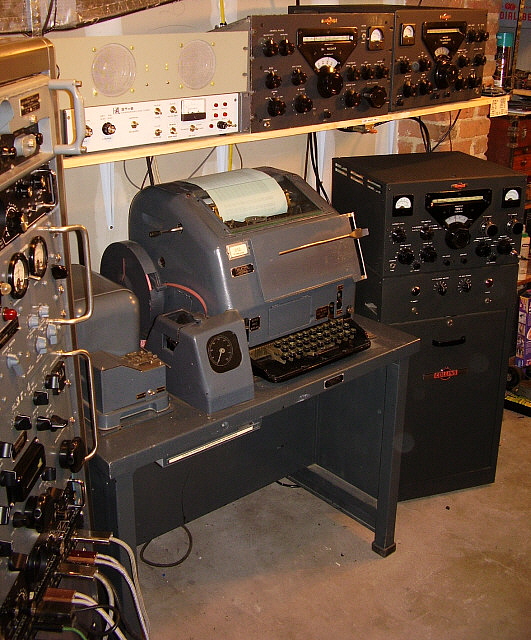
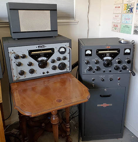
So, why didn't I solve this problem earlier? Maybe I'm obtuse but, since the KWS-1 and 75A-4 aren't the only station equipment around here, there really wasn't a pressing need to find a solution to this problem since the other stations could be used. Quite a while later, with an increased interest in my long-ignored 75A-4 SN:850 along with the possibility of writing up and expanding its refurbishing process into a "restoration" article, had me thinking about setting up and operating the complete Collins station I had over 50 years ago. But, the KWS-1 still had the oscillation problem on 80M from the 2021 RTTY set-up. I finally had to put together the clues that the KWS-1 worked fine into a dummy load so it had to be something with the antenna set up. Changing the 1:1 SWR to 1.5:1 SWR was the "break-through" since that eliminated the oscillation. It had to be the coax - that was all that was left. 
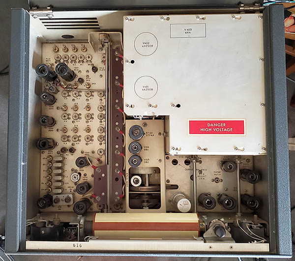
Other Things - I did find that the housing and mount for the +2000vdc input to the back of the KWS-1 was extremely loose. I found that the two screws and nuts that mount the internal part of the assembly to the chassis had backed-off and were almost ready to fall off the threads. Retightening these mounting screws and nuts got the +2000vdc housing secure and now the +2000vdc plug firmly connects to its receptacle. This has apparently been loosening up for quite a while since I've been noticing that the +2000vdc plug was always loose and so was the housing, I just never checked why. KWS-1 and 75A-4 station set-up is further down in the section "On the Air Again" |
Details on Two 75A-4 Receivers Once again, it's hard for me to believe that I've owned 75A-4 SN:850 for over 55 years. Of course, it wasn't even a new receiver back when I bought it in 1970. SN:850 was the third communications receiver I purchased. I had a 1934 Patterson PR-10 when I was 15 years old. When I found a derelict RAO-3 and got it working, then I got my ham license. I was 19 years old then. The RAO-3 was quickly replaced with this 75A-4 SN:850 and the difference in performance made me a longtime fan of vintage Collins gear, especially the A-line, the military receivers, the V-line and the KW-line. SN:850 has been through a lot over the past half-century but the most embarrassing situation was when SN:850 stopped working (in 2011) and I just put it into storage, never repairing it. Finally, after 14 years of storage at two different QTHs, I gave the receiver a thorough "going-over" and refurbishment for 2025. I just couldn't believe all of the things I found wrong with the receiver,...some had been problems I certainly was responsible for,...but other problems had been present since before I purchased the receiver. Anyway, SN:850 is doing fine now and ready for another half-century of operation on the ham bands,...well, maybe. 75A-4 SN:4470 was just a "lucky find" that was purchased off of an Internet "Antiques" posting back when the Internet was just getting going and long before eBay became the "go to" place for buying vintage radio items (here in NW Nevada there are only three ham swap meets per year and only one of them could be considered "sort of large.") It was a bargain-priced 75A-4 that had a lot of great features but was in "almost derelict" condition, having never had anything nice done to it, not even any cleaning performed. I refurbished SN:4470 in the 1990s and it's still a great performer. Looks pretty good, too. |
|
75A-4 Receiver - Considered by many radio amateurs to be the finest vintage "ham bands only" tube-type receiver ever produced. The Collins 75A-4 was introduced in 1955 and manufactured up to about 1958 or so, with around 6000 receivers for total production. The 75A-4 was the ultimate evolution of Collins' 75A Series of receivers that had started production in 1947 with the 75A-1 (the 75A was the initial 1946 version that didn't have a Noise Limiter but it may have been a prototype and not an actual production receiver.) The 75A-2 changed the PTO type and the styling of the escutcheon. The 75A-3 had the capability of NBFM with the optional adapter and a single mechanical filter with the availability of a second mechanical filter as an option. Of course, the 75A-1, 2 and 3 weren't designed for SSB although a post-production kit to add a product detector was offered for the A-3 (installation required removing the "winged emblem" for the switch shaft.) The 75A-4 was designed for SSB reception and had a few other features that greatly enhanced performance. An "urban ham legend" has persisted for decades that production consisted of the first 5000 receivers built in the USA and the last 1000 receivers built in Canada. It's more likely that just some 75A-4 receivers were built in Canada and their serial numbers seem to be sporadically placed in the SN roster. The selling price seemed to stay in the six hundred dollar range for most of production, $695 was the typical price in the later fifties. Circuit Details - The 22 tube circuit featured a 3.1 kc mechanical filter and a product detector, making the 75A-4 ready for SSB - but it could also copy AM quite well since a separate AM envelope detector was also provided. For better AM copy an optional 6.0 kc mechanical filter could be purchased or, for CW, an 800Hz filter was available. Later, other mechanical filter frequencies were offered, e.g., 500 cycle for CW, 2.1 kc for SSB, 1.5kc for RTTY, plus others. Up to three mechanical filters could be installed, providing optimum selectivity for CW, SSB or AM. Frequency readout was "Collins accurate" and sensitivity was competitive. Audio was quite good because of the envelope detector used on AM but the 6.0kc is necessary for adequate bandwidth unless only one sideband is listened to on AM (selecting one sideband or the other makes for better AM copy even when using the 6kc filter.) Passband Tuning - This was a new type of control that allowed the BFO to remain tuned to the desired signal while slightly changing the tuned frequency of the receiver via the PTO. This was accomplished by having the BFO tuning mechanically coupled to the PTO tuning (the BFO shaft control actually rotates the body of the PTO while the dial drive gears keep the PTO shaft stationary, thus only the PTO frequency and the Beat Oscillator frequency are changed.) As the Passband Tuning was adjusted the BFO and PTO were tuned in opposite directions which allowed the desired signal to remain tuned in relation to the BFO while slightly changing the tuned frequency. This could be done in other receivers of the time but would have required the operator to adjust both the tuning and the BFO simultaneously. Passband Tuning accomplished this with just one control.75A-4 Variations 1. The 4:1 vernier knob was an early option (purchased separately) that allowed for very smooth tuning in an almost bandspread "feel" to the tuning mode. Collins claimed the 4:1 vernier dial gave the equivalent of 28 feet of tuning "bandspread." Later models had it installed "from the factory" (supposedly from serial number 4200 and up, however this must have been a very popular option since it's rare to find a 75A-4 that doesn't have the 4:1 vernier reduction knob installed.) 2. Early receivers had a N-Type connector that was replaced with a SO-239 antenna connector (many SO-239 installations were probably owner replacements of the N-connector) while later receivers had a BNC antenna connector. 3. There are variations in the beveled edges of the front panels with early panels appearing "rolled off" or "rounded" while later receivers have a very small bevel and appear "squared-off" rather than the more "rounded" look of the edges of earlier panels. 4. Very early front panels had NOISE LIMITER and AM CW-SSB nomenclature not inline while later front panels did have these nomenclatures "in line" (this seems to be found on serial numbers below 500.) 5. S-meters found on receivers with very high serial numbers will have "all black" printing on the scale similar to the S-line meters. The majority of 75A-4 S-meter scales will be black from 0 to S-9 and with red for the "DB over S-9" part of the scale. A few (very few) S-meter housings had vertical ribs below the glass and these meters were apparently supplied by Simpson. The Simpson meters also had a lighter red, made up of "cross-hatching," for the "DB over S-9" part of the scale. 6. Note on the two 75A-4 photos below, on SN:850 the small knob to the left of the tuning knob is marked "DIAL DRAG." Then note the photo of SN:4470 that this same control is marked "DIAL LOCK." Later receivers, supposedly those that had the 4:1 tuning knob from the factory, were marked "DIAL LOCK." How the mechanism works is the same, just the name was changed. 7. Early models have the common, relatively small rubber feet mounted with phillip's head screws, nuts and secured with green Loctite. Late models use rubber bumpers for feet, stud-mounted with external-tooth lock washers and green Locktite on nuts (the rubber bumpers are the same as those found on the 32V transmitters.) 8. Earlier models (probably below SN:1000) had a fairly high hum level (a 1955 service bulletin covered this) and problems with the AVC (the AVC change was a production Engineering Change Order or ECO, not a service bulletin.) The Service Bulletins are based on Collins ECOs incorporated into production to correct performance issues. Also, there were a couple of Service Bulletins for upgrades for the Noise Limiter, one for the Q-Multiplier-Rejection Notch (only if the "notch" didn't meet spec) and the fairly involved S-meter adjustment potentiometer modification. There were four Service Bulletins issued between 1955 and 1957 that contained several upgrades each. There were many more "upgrades" that were actually ECOs that were incorporated into production but not specifically thought to be important enough for an official "upgrade service bulletin." Expect to find several differences under the chassis if comparing an early 75A-4 to a late-version 75A-4. Collectors usually favor the later serial numbers (higher than 4000) since all electronic up-grades and ECOs were in place by that time. However, Collins offered up-grade kits which many owners installed themselves, so serial numbers alone do not tell you the performance capabilities of a particular 75A-4. But, remember that not ALL of 75A-4 engineering changes are covered in the Service Bulletins, just a few are. Comparison of the 1955 75A-4 schematic to the 1957 schematic will reveal many more changes. 9. There were also a few options that could be purchased separately for the 75A-4. The 4:1 knob kit was Collins pn 307E-1, the Low Pass Filter (for VHF TV-BC interference) was Collins pn 35U-1 and the Noise Blanker kit (installed behind the PTO) was Collins pn 136-C. As mentioned, the 4:1 knob is common, the LP Filter is seen once in a while and the Noise Blanker is a rare option that was fairly involved to install. |
75A-4 SN:850 - I bought this Collins 75A-4 in late-March 1970 (I was 19 years old at the time.) I had just received my Novice license earlier that month and was attempting to use a WWII Wells Gardner RAO-3, as the station receiver,...and this was on 15M using a rotatable dipole antenna. After several days of calling CQ and only working two stations and "loosing" all of the other stations halfway through the attempted QSO, I decided I needed a receiver newer than one from WWII, at least on 15M (Novices were crystal-controlled CW then and limited to 75 watts input power, so calling CQ and tuning around to find the reply was standard procedure.) I'd never been to Ham Radio Outlet in Burlingame, California. It was about an hour's drive from where I was living then (San Pablo, CA.) When I got to HRO, I found they had an ample supply of used receivers for sale. A Hammarlund SP-600 (without a cabinet) caught my eye and I was giving it a close look when Scott Richie (one of the HRO employees) came over and said, "You don't want to buy that receiver. You really should buy this one,..." and he pointed to the 75A-4. "You'll hear a lot more stations on this receiver, it's a good one," and, of course, I noticed that it was "ON SALE" and priced $100 less than the SP-600. I took Scott's advice and purchased the 75A-4 for $190, the matching 270G-3 for $10 and an original manual was "thrown in." Of course, Scott was right. I started working stations with every CQ using the 75A-4. I thought SN:850 had all of the Collins upgrades installed. As it turned out, SN:850 only had a few of the Collins upgrades. It also had a few owner-ideas incorporated into the circuitry. Sprague Orange Drops were installed replacing the Sprague "Black Beauties" but they were installed using heli-coil soldered butt-joints with very long leads. It was a well-cared for receiver,...but, it was only 15 years old at the time of purchase. The 2025 refurb resulted in a couple of "mod surprises" to be discovered. Details further down. |
|
75A-4 SN:4470
- Sharon KK7EI (the XYL) spotted this 75A-4 on an Internet discussion group for
"Antiques" - just a general sort of listing of various old things for sale. This was
around 1997. I was downstairs in the museum (WHRM in Virginia City) so
she came down and said, "I saw this listing on 'Antiques' that said there
was a Collins receiver for sale for $200,...nothing else, just a phone
number. This listing just came up, so you better call NOW!" And, I did.
I asked the guy what kind of Collins receiver he had,...he replied, "It
says 7 - 5 - A - 4."
I asked why he was selling it and he related that it was too big for his
desk and didn't work very well. I didn't ask any more questions and just
said that I'd take it and that I'd mail him a MO that day (this was long before PayPal.)
I had to send the MO to the state of Virginia, so the 75A-4 would be
traveling quite a distance to get here.
The guy called back about a week later to tell me that the 75A-4 had shipped. He asked, "What is this radio anyway? I had a bunch of other calls offering me more money for it and telling me that I was selling it too cheap. But you were first to call and paid for it quick so you got it and it's on the way." I told him that there's no way to determine sight-unseen (no photos) what I'm getting, saying, "It might be worth $200 or maybe more. But could also be that it's a junker and only good for parts. I won't really know until it gets here." When it arrived, I found the "good news" was that it had all three mechanical filters installed (6.0kc, 2.1kc and 500hz) and it had the 4:1 reduction knob. Its serial number was way over 4000 and the receiver was complete. The "bad news" was that it was extremely dirty (I mean really, really filthy!) It barely functioned. The finish was fairly rough with one big scratch on the front panel. It needed quite a bit of work and had a strange mechanical buzzing noise that turned out to be one of the filter chokes. So, it needed a fairly involved rebuild. Afterwards, with new filter caps, black beauty cap replacements, tightening the laminations on the "buzzing" choke, quite a few NOS tubes and a full IF/RF alignment, it functioned like a good 75A-4 should,...looked pretty good, too (a few scuffs and nicks, including a very large, front panel blemish over the S-meter, but still very nice overall.) |
|
Modifications - The four official Collins "75A-4 Service Bulletins" are certainly worth investigating and deciding if they should be installed now, almost 70 years later. If you have one of the early 75A-4 receivers, then some of the Collins upgrades probably should be installed if you plan on using the receiver. But, if it's a very early, "all original, collector" receiver, then you might decide to keep it all original (there are very few all original, really early 75A-4 receivers anymore,...in fact, there are very few 75A-4 receivers of any vintage that are "all original" anymore.) All of the official Collins' upgrades were installed in production receivers by SN:4000 or so. When looking over the Collins upgrades, you'll probably find that some are necessary for good performance and others are "if you have this problem then" types. There are some later, ER-type mods that are quite subjective in their supposed improvements. There are several "non-Service Bulletin" Collins upgrades that are actually Collins ECOs or Engineering Change Orders that were circuit improvements that were incorporated into production but were never issued as "official upgrades" via Service Bulletins. The B+ blocking to the mechanical filters is one such ECO that can be found by looking at the 1955 schematic and comparing it to the 1957 schematic. The change of R86 from a 1/2W CC resistor to a 1W CC resistor (AVC B+ load) was another ECO (due to heat-damage to R86 because of operating the receiver on high AC line voltages of 120vac and up.) There are many other minor ECO changes that require a detailed examination of the schematics or by examining an "early version" receiver under the chassis next to a "late-version receiver" under the chassis. ALL of the non-Collins mods out of magazines from the 1970s should be avoided. These were written at a time when there was very little regard for the 75A-4 and the mods show it. Any non-Collins mod should be carefully researched before hacking up a nicely performing receiver. It's not uncommon to find highly modified receivers that actually have fundamental component problems or misalignment causing the issues that the mod was supposed to cure. Be sure the 75A-4 is fully functioning correctly before judging that it "needs to be modified." General Performance - In use, the 75A-4 is an excellent receiver. Its ability to eliminate adjacent frequency QRM is amazing. Using the Passband Tuning, an offending signal can be "dropped off" of the edge of one sideband while another offending signal on the opposite sideband can be eliminated using the Rejection Tuning. And then, maybe just switching to a more selective mechanical filter might eliminate the QRM. This ability to effectively eliminate several interfering signals simultaneously is impressive and makes the 75A-4 a valuable addition to a vintage ham station operating in any mode of reception. Dial accuracy is "to the kilocycle" and frequency drifting is minimal. The Noise Limiter works well on pulse noise, the audio reproduction is decent. The 75A-4 is very easy to work on since there's ample space under the chassis and only a few places are subject to "component congestion." There aren't very many mid-1950s era receivers that can still be used today, especially on SSB, and certainly the 75A-4 is one very special "vintage tube-type receiver" in that it can still provide reliable communications in just about any mode. |
SN:4470 Only Needed a Servicing for 2025 |
2025 Servicing of SN:
4470 - I haven't used this 75A-4 in about three years. It
was last
used for a RTTY station with a HAL-6000 TU and a Model 28 Compact (I
also used my homebrew RTTY TU during these experiments.) The
receiver was working fine at that time but after a few of idle years
I thought it would be a good idea to go through the servicing just to see what
would be found. First, is to set up and place the receiver in operation.
SN:4470 seemed to operate fine with no really apparent issues except for
an extremely noisy AF Gain control. This requires removing the bottom
cover to
give the AF Gain pot a shot of DeOxit. As long as the bottom cover is
off, then an inspection can be performed, the other pots and switches
given a shot of DeOxit and just a general cleaning. The pots are
actually mounted to the front panel but are accessible with the bottom
cover off. I'll have to inspect
what I did to SN:4470 about twenty years ago to get it operational then. In the initial testing, I operated the receiver for three hours just tuned to 20M. I wasn't monitoring the operation but, every time I did check, operation seemed normal. After the power was shut off, I decided to test all of tubes (after a waiting period of a few hours.) To my complete surprise, when I lifted to lid to start pulling tubes, I noticed that the 0A2 regulator tube wasn't present, just the empty socket (I had robbed it for another project, I guess.) This means that the +150vdc regulated voltage to the PTO in the receiver was operating at about +190vdc. Before testing the tubes, I installed a 0A2 and did another operations test on the 75A-4. Everything worked fine, in fact, the receiver sounded a little better (my imagination, I'm sure.) But, on to testing the tubes. All of the tubes tested good, not as NOS, but certainly at least 50% over minimum acceptable. The exceptions were the AVC amplifier tube 6BA6 showed a short (high leakage,) the 12AT7 was marginal and the 12AX7 also tested at just acceptable. These three tubes were replaced with tubes that tested at least 50% over minimum acceptable. The 75A-4 was given another one hour "burn-in" to see if anything developed but the receiver seemed to operate just fine. However, when initially powered-up the next day, the dial versus frequency was 50kc off. Changing bands immediately corrected the problem but it would return at the next power-up. The band switch must need cleaning (I've never performed that task.) Next, the AVC was acting erratically in SLOW and seemed to not work in FAST. Actuating the AVC switch would temporarily correct the problem but it would come back in less than one minute. This was caused by the 6BA6 AVC amplifier tube that I had just installed (and that had tested good.) I installed a NOS Sylvania 6BA6 and that corrected the AVC problem (tube testers aren't 100% at finding problems, the tube functioning correctly in the circuit is the "final test.") I let the 75A-4 "burn" for another hour with no new problems developing. Bottom Cover Off Inspection - The bottom cover removal revealed that I had replaced all of the Sprague "Black Beauties" with CDE 715P Orange Drops (nice!) The two 150vdc electrolytics were new replacements but the multi-section appeared to be a vintage replacement (Sprague 40uf x 3 at 450vdc with a 1964 date code.) The workmanship was excellent, so no rework is necessary. I gave the band switch the DeOxit treatment and also gave the same treatment to the AF Gain pot. The chassis had a small amount of dust that was removed with a paint brush. |
|
|
Bottom Cover Rubber Bumpers
- The later 75A-4 use rubber bumpers for the four feet on the bottom
cover. I noticed when removing the cover that the two front rubber
bumper studs felt like they were stuck and the cover was somewhat
difficult to remove. I checked and the mounting nuts on the two forward
rubber bumpers interfere with the front sheet metal parts of the
chassis. Also, the right side front bumper comes very close to hitting the
headphone jack. I measured and the easiest solution was to slightly move
the two front mounting holes. The right hole had to be move forward about .060"
and the left hole had to be moved .060" to the right and forward. I used
a small round file since the material removed was just a slight amount.
Now the bottom cover doesn't interfere and can be easily removed or
installed. The headphone jack was remounted to have the contact arm
vertical to provide good clearance for the rubber bumper stud. I'm sure
this problem is not on every 75A-4 with the rubber bumper feet. It's
certainly due to slight assembly variations in the chassis versus the
front panel and the bottom plate on just this receiver. Extra Mechanical Filters? - I found a plastic bag in the 75A-4 cabinet that had two mechanical filters inside. One MF was a 1.5kc and the other MF was a 3.1kc. Both were the correct type for the 75A-4 but, where'd they come from? I inherited them from my old friend W7TC. He had owned a very high serial number 75A-4 (SN was over 5000) that he, for some unknown reason, sold many years before he became SK. I inherited several boxes and bins that were TC's "junk boxes." He probably had forgotten that he had stashed the extra MFs where I found them, in his spare parts boxes. I put each MF into a plastic bag and then both bags into another plastic bag and stowed them in my 75A-4's cabinet. I decided to do an experiment with the MFs. I replaced the 2.1kc MF with the 3.1kc MF. Then I replaced the 500hz MF with the 1.5kc MF. Now, SSB sounds much better with a 3.1kc bandwidth but if I need more selectivity, the 1.5kc MF is wide enough to still allow easy SSB copy. On CW, the 1.5kc MF is narrow enough for how little CW QRM there is today (except during a CW contest) and for RTTY it gives a better bandwidth since the 500hz MF seemed a little too narrow. |
Wrap-up - SN:4470 is a good example of a late-75A-4 receiver. About the only "cutting and hacking" that was done was that a former owner installed two RCA phono jacks just under the rear terminal strip where the loudspeaker connection terminals are. There's nothing connected to the RCA jacks, they're just there and the installation job looks professional so I left them alone. That front panel blemish or scuff over the S-meter shows up prominently in photos. It's really not that visible. I touched up the scratch during the first rebuild back in the 1990s. Anyway, a new 2025 photo is above-left. |
Refurbishing SN:850 after 55 Years |
What About SN:850?
- I've owned this 75A-4 for 55 years. Being kind of young when I got it, I did stupid
things to the receiver,...like changing the fiber terminal strips on the
rear chassis to gray plastic military-type terminal strips. I
reinstalled the original fiber terminal strips back about 20 years ago. Up until
recently, I thought that SN:850 had all of the Collins upgrades
installed when I bought it back in 1970. But, I still did a couple of ER mods,...one was okay (AVC) and one was immediately removed after
testing it (SSB distortion.) Probably about 14 years ago, SN: 850 just quit
working (I was in Virginia City at that time.) I hate to admit it but I
didn't even check out why the receiver quit working and just put this 75A-4 into the storage mode.
Even after the move to Dayton Valley, it was just put into a different storage area.
To this day, now in 2025, I haven't looked at it to determine what the problem is. I'm sure
it's just a tube but I'll have to put it on the bench to see what's
going on. More info when that happens. It's semi-buried in the upstairs
storage right now. Mar 20, 2025 - I got SN:850 out of the upstairs storage area. It required quite a bit of moving things around to get access to it but it seems to have survived being in the ham shack closet over the past 12 years in good physical condition (or so I thought) but it did acquire quite a coating of dust. It hasn't had power applied in at least 15 years but since I did replace the filter capacitors just a little earlier than that, I didn't expect any problems in power-up (other than that it wasn't working.) Preliminary Testing - I connected a 270G-1 loudspeaker and hooked-up the Pixel Loop
antenna. AC power applied and the lights came on but nothing came out of
the speaker. With the AF Gain increased I could hear the B+ through the
audio and that indicated the problem was in the front end. I turned on
the CAL and there was no response. The 4:1 tuning knob was EXTREMELY
DIFFICULT
to move, almost like it was stuck. It felt like any lubrication must
have solidified into somewhat malleable concrete or maybe
there was just a lot of dust (I bet the lube has dried up and hardened.)
Finally, I lifted the lid. What do I see? One of the 6BA7 tubes is
missing. Did I rob that tube? I don't think so because the only place
that 6BA7 tubes are used (around here anyway) is in the 75A-4 and
I didn't need one for SN:4470. I must have tested the missing 6BA7,
found it was bad, never installed a replacement and just left the tube
shield in the receiver (so I must
have at least troubleshot the problem back in 2011.) Anyway, I got
out another 6BA7 tube and installed it. The 75A-4 came to life and
started receiving stations on 20M. I tried 40M also with several
stations heard. I decided to let SN:850 remain in operation for a couple
of hours to thoroughly warm-up everything and to get the electrons
flowing through the circuitry once more. I also thought that the heat of
operation might soften the lubrication grease and ease the tuning. It
did loosen the tuning up a little but there's still A LOT of resistance
in the tuning action.
|
Mar 21, 2025 -
Disassembly of the 4:1 Reduction Tuning
Mechanism - The
4:1 reduction knob needed to be removed in order to lubricate its vernier
mechanism. I copied the Collins kit instructions for the 4:1 knob off of
the Internet (CCA website) since
I'd never removed one of these before. Removing any of the set screws used in
the mechanism will require a #99-62 spline wrench or a Bristol wrench
0.050" - all six sets screws involved are the same size. I loosened the two set screws
that secure the knob to the mechanism shaft. But, would the knob easily
come off the shaft? Of course not. I put on the DIAL DRAG and worked
with the knob gently rocking and pulling it until it finally came off the
shaft. It was apparent that the shaft was marred from excessive
tightening of the set screws in the past (I had loosened the set screws
so the marring was from years before.) Once the knob was off then the rest of the
mechanism was easy to remove. Two screws mount the mechanism to the front
panel. Two set screws secure the drive gear to the receiver's tuning
shaft. Two set screws secure the front retaining plate of the pinion
shaft in its bearing. Three screws allow removing the front bearing panel for
full disassembly. There's an anti-backlash spring that wraps around the
pinion gear hub.
Once the knob was off it was fairly obvious that the problem was excessive black grease had been slathered everywhere and that grease had now dried into a hardened glue. Observing how the mechanism was supposed to work and having the Collins instructions let me know how to fully disassemble the mechanism. The instructions aren't "step-by-step" but they are detailed enough for taking the 4:1 vernier apart and putting it back together. Since these instructions were written in the 1950s, carbon tetrachloride is indicated as the cleaning fluid. I'm not even sure you can buy carbon tetrachloride anymore. I tried WD-40 as a degreaser but it didn't even cut the old black grease. I had to use naptha (similar to kerosene, used outside, of course) and even that took some scrubbing to remove all of the dried on grease. The naptha was then washed off the WD-40. I had to "dress-down" the marring on the shaft on both the receiver tuning shaft and the 4:1 shaft using a fine jeweler's file. Other marring and nicks were removed using the jeweler's file. I had to ream the knob hole to .250" to allow it to fit correctly onto the vernier shaft (I don't know how this knob was ever supposed to fit, the hole was several thousandths under-size - I guess it fit just like how I found it,...wedged and forced onto the shaft.) Once all of this "sizing" was done, then the vernier mechanism could be "dry assembled" to see if anything didn't fit correctly. I used red wheel bearing grease very, very sparingly, only coating the gear teeth and the bushings. The vernier assembled easily and once installed the receiver tuning was now super-smooth and very easy to manipulate. |
March 22, 2025 - More Degreasing Requires More Disassembly - It was obvious that I had NEVER really thoroughly cleaned SN:850 in the 55 years of ownership. I dismounted the front panel to clean the old grease from the two split-gears for the tuning drive. I had to remove the KC dial to clean the gears and to also clean both the back and front of the KC dial (there were actually dried grease spots on the back of the KC dial from someone in the past greasing the split-gears, which really shouldn't ever be done to split-gears.) After cleaning the grease, I used light oil to lube the split-gears. I also applied one or two drops of light oil to the bearings involved with the tuning gears. I took the bottom cover off also. I noticed that all four original rubber feet were deteriorated to the point that they actually all had a large crack from top to bottom and all the way through to the hub - new rubber feet needed. Actually, the later 75A-4 receivers used equipment rubber bumpers with the threaded stud molded in, not the common rubber feet mounted with screws and nuts. These rubber bumpers are much better at supporting the receiver and they are easily available. I bought a set off of eBay for $10. Replace the Replacement Capacitors? - About 15 years ago, I replaced the capacitors that had been installed in the past (Sprague Orange Drops installed with heli-coil butt joints and long leads) with "yellow jacket" type of polystyrene dielectric caps (and these are also good quality capacitors that I installed correctly.) But I now wanted to replace the yellow polycaps with better quality polypropylene dielectric CDE Orange Drops, also installed correctly. I had also replaced all of the electrolytic caps but I had used individual axial mount capacitors to replace the filter multi-section though I left the original replacement unit mounted to the chassis. I'm sure the multi-section was a replacement Sprague unit since it was dated-coded 1962! I wanted to replace those individual 47uf electrolytics with a modern Mallory newly-built multi-section capacitor (available from Antique Electronic Supply.) Since I have to order the new multi-section along with some 716P 400vdc Orange Drops and I have to order the correct (later style) rubber bumpers, it's going to be awhile before SN:850 can be reassembled. I can finish the cleaning, reassemble to the point where the receiver is ready to be "re-capped." March 23, 2025 - Next, is to test all of the tubes in SN:850 so I know what the condition is of the tubes and to replace any that are bad or marginal. All tubes tested well above minimum acceptable except for one of the 6BA6 IF amplifier tubes showed high leakage (a short on the tester.) I had to use a razor blade to remove all of the masking tape on the tubes ("V-number" designations) that had literally been baked on for decades. The tube shields are mostly marked "COLLINS" as originals should be. There were two IERC types, a black wrinkle finish no-name type and two silver finish types used for the PTO tubes. Several of the black COLLINS types were severely scratched and marred for some reason. I touched up the scratching with a black Sharpie. As I replaced the tubes, I used a small paint brush to apply a light coating of DeOxit to the tube pins and then worked the tubes in and out of the sockets a couple of times to clean the contact area. |
Under Chassis Inspection Turns Up Unexpected Issues - Since I had to wait for the new capacitors to arrive, I wanted to closely inspect the chassis and see what I've done and what had been done in the past, pre-1970. 1. I know I installed the common post-Collins AVC mod and that mod did work well. I also installed the SSB distortion mod and immediately removed it since it achieved the reduced distortion by reducing the gain at the product detector (the difference between the output in SSB/CW versus the output in AM was disturbing, almost shocking.) 2. The receiver had a 6BZ6 RF Amplifier tube installed when I got the receiver 55 years ago. I installed a 6DC6 back then and it seemed to raise the background noise so I reinstalled the 6BZ6 and assumed there were mods to the RF amp. But, an inspection now has revealed that the RF Amp circuit is stock so I'll try a 6DC6 again. A comparison showed that WWV 15mc was S-9 with the 6BZ6 and it read S-9+20db with the 6DC6. I think what happened was back when I got the receiver the 6BZ6 had been installed because the owner didn't want to buy a 6DC6 and he had the 6BZ6 on hand. I had thought that the substitution was for performance but it obviously wasn't (additionally, I never found any mod that recommended a 6BZ6 sub for a 6DC6 for the 75A-4.) 3. Found that C114 had one lead broken. It's a ceramic disk, so it will be replaced along with the cap change. (C114 is a tube heater bypass so it's not critical.) 4. C54 had never been changed. It was still a striped molded paper dielectric capacitor (a "Brown Beauty" type.) It's buried under a cluster of other components which is why it was never changed. I might have to remove the side panel to access the capacitor and do the replacement. The leads appear long enough that it might be possible to replace C54 without disassembly, but if not, then the side panel will have to be removed. 5. For some reason the grid bias filter on the 6AQ5 was changed from a 1.0uf cap to a .47uf. There should be slightly better filtering of the grid bias voltage with the 1.0uf so that's what I'll install. (I had been using the 1957 schematic. I finally found the 1955 schematic and .5uf is correct for the grid bias filter - on early models. I'll install a 1uf since that was a Collins ECO upgrade.) 6. The other conflicting components were all part of Collins upgrades or the AVC mod so those will remain the same values. One exception is on the 1st AF amp using a 750K (an obvious replacement part that was "tack-soldered" in place) where it should be a 390K. I correctly installed a 390K 1/2W CC AB resistor. 7. I functionally tested the 75A-4 at this point. The AF gain control needed a shot of DeOxit to quiet down the "scratchy-ness." Since I had the KC dial off for cleaning, I checked the PTO output and set it for 2.455mc or mid-scale. I set the KC dial for 0.00kc and then tightened the set screws. The dial read off by about 3kc so I used the CAL and set the MC dial for 14.5mc zero-beat and then set the KC dial to 0.00 and snugged-up the set screws. I might have to change this adjustment during alignment. |
|
photo left: 75A-4 SN:850 after
the 2025 refurbishment, top of chassis. Nothing changed here except a
couple of tubes. As can be seen, the chassis is pretty clean. I didn't
do anything except remove the dust that had accumulated from the "closet stay." Not all of the tube
shields are correct "Collins" types. There are two IERC types on the
12AX7 and the 12AU7. Also, one other shield is an unidentified black
wrinkle finish type. 2025 photo
photo right: 75A-4 SN:850 after the 2025 refurbishment. The orange drops are 716P type so they are more "flat" than the 715P types that I used for SN:4470. Also, the 716P caps are rated at 400vdc while the 715P are rated at 600vdc. The yellow wire (really stands out) is part of the AVC mod. The installation of the 40ufx3 multi-section electrolytic really cleaned up that area under the chassis. The non-original hole in the chassis below the blue-color bias supply filter capacitors was where the former owner mounted a fiberboard with terminals for two 47 ohm 2W CC resistors in series with the power transformer HV windings and the 5Y3 rectifier. I removed that mod leaving the hole. 2025 photo |
|
March 28, 2025 - The CDE
716P Orange Drops came today along with the new Mallory 3 x 40uf
multi-section electrolytic. I started by removing the left side panel to
allow better access to C54, the "Brown Beauty" that was never replaced.
Removing the side panel helps quite a bit but it's still very difficult
to remove C54 and, of course, the 716P caps are 400vdc caps so fitting
one into a space where a
200vdc cap was installed required a slight change in location around the
tube socket by 90º to have the necessary clearance. Lead lengths
remained about the same. Two other capacitors are on this side of the
chassis and after they were replaced, I reinstalled the left side panel. I had the 75A-4 "on its back" for the rest of the capacitor replacements since this makes it easier to do the rework. I had to double-check the capacitor values on this side of the chassis to take into account the AVC mod. Also, that the 6AQ5 grid bias filter that was the earlier 1955 value. As I started to check on the correct installation of the caps, I started to discover connections that didn't agree with the schematic but these mostly turned out to be some of the Collins ECO-type upgrades. Finding the 1955 75A-4 schematic has been a big help in clearing up the component value and wiring confusion. Mar 30, 2025 - There was a "owner-engineered" mod that added a small fiberboard with four terminals with two 47 ohm 2W CC resistors mounted near the center of the chassis. These two resistors were in series with the HV winding of the power transformer to the 5Y3 rectifier plates. I imagine this was to slightly lower the B+ voltage due to high AC line voltages or maybe to protect the HV winding if a short-circuit developed. At any rate, it wasn't part of the original design or any Collins upgrade, so it was removed and the transformer secondary rewired as original. And, just to make it interesting,...one of the wires going from the terminal board over to the 5Y3 tube socket terminal hadn't been soldered,...wrapped around the 5Y3 socket terminal but not soldered (and it had been that way for over 55 years! Wow!) NOTE: I always operate vintage equipment using a line bucking transformer to lower the 122vac line voltage that I have here down to 115vac. Essentially accomplishing the same B+ reduction externally without modifying a vintage electronic device. Mar 31, 2025 - When I installed the three individual axial-mount electrolytic capacitors 20 years ago, I used a tie-point strip ground and added a 16ga. TC wire to the ground lug on the S-meter pot mounting plate. I then soldered the negatives of the electrolytics to this grounding lug and connected the positives to the tie-points and to the three B+ lines. All of this was removed since I now had a new Mallory multi-section electrolytic to connect into the circuit as it was originally done.Close inspection of R86 (AVC B+ load resistor) revealed that it had gotten very hot over the years, it was slightly bulging and discolored. Originally, this was a 39K 1/2W CC but later in production it was upgraded to a 1W CC. The original resistor had changed value to 31K, so not too bad (20% change.) I installed a 39K 1W CC. This resistor dissipation change was a Collins AVC ECO, not a Service Bulletin upgrade. The new multi-section electrolytic was connected into the circuit. Tested operation and let the receiver run for about one hour. NOTE: I had to remove the bottom cover from SN:4470 to have some sort of visual reference as to what the chassis circuitry of a stock 75A-4 should look like. Of course, I had to keep it in perspective that SN:850 is an early 75A-4 and will have some differences. But, overall, having a stock receiver as a reference has been a tremendous help. |
IF/RF Alignment
- Since SN:850 has been around here for a long time and has never been
in poor storage conditions, it wasn't surprising that the alignment was
one of those that just moves the adjustment to confirm that it already
was set where it should have been. There are a couple of things to watch though. One is the
Crystal Oscillator "trim" where the manual says that errors between
bands can be adjusted out using the inductive adjustments. To a limited
extent, especially on the lower bands, this is absolutely possible. On
the two 10M and the 11M band just getting close is about all I could do
before the crystal oscillator would quit oscillating. I set them as
close as was reasonable to make sure the oscillator would "start" on
power up. Sometimes if the L adjustments are set too close to "drop
out" the oscillator won't "start" on power up and the band will be
non-operative. So, I didn't set any of the L adjustments close to "drop
out." In fact, the high 10M crystal oscillator wasn't even
oscillating at first until the L was adjusted correctly (I guess I
never listened to 29.0mc and up.) The other oddity is adjusting the Lo 10M band first, then the 11M
band and finally the high 10M band. Also, since the 11M and high 10M
bands only have one trimmer to adjust, that adjustment is made at the
center of the band coverage. One other note is that for the IF
alignment, the bottom cover must be off because the two IF transformers
have slug-trimmer adjustments on the bottom and on the top. The RF alignment should
have the bottom cover installed. All other adjustments are on top of the
chassis. Performance - I don't know if I would go so far as to say that this is the best that SN:850 has ever performed,...but I know this is probably the best overall condition that this receiver has been in for a long, long time. The other thing is,...I have scrutinized under the chassis more than ever before. I think I've found every questionable connection and I've removed all of the non-Collins, unauthorized circuitry (with the exception of the ER AVC mod.) So, I'd say that I now know SN:850 better than I ever had in the past half-century. |
|
Wrap-up - As for appearance, a new 2025 photo is above-right. I can't believe how dirty this receiver was, especially the KC dial. It now appears white like it should. I guess that SN:850 could be considered a very nice condition "survivor" that's a good example of a fairly early 75A-4 that has been used fairly regularly but never abused, maybe ignored a few times for a little while,...but never abused. |
Other Information About Collins ECO-type Upgrades and Unauthorized Modifications |
Service Bulletins - At the time,
in 1970, I guess I was
the only person interested in the 75A-4 or the KWS-1 that Ham Radio
Outlet in Burlingame knew about so they
sold me an 800hz mechanical filter for $10 and, a little later, a 6kc mechanical filter
for $10 ("What do you want one of those for?" was their response to my
question if they had one.) These MFs were just loose, rolling around in a drawer up front
at the counter. Since HRO thought that nobody was interested in these old relics
anymore, they gave me all of their original Collins Service Bulletins paperwork. All of the papers were
official, from Collins and had all of the information on the Collins
recommended upgrades. This was probably around 1971. Later that year,
I had some questions on the KWS-1 that I sent to Collins Radio Company. Their reply
was to send me copies of all of the Collins upgrades for both the KWS-1
and for the 75A-4. Between the two sets of Service Bulletins, originals
and copies, I believe I
have all of the official Collins information on both pieces of equipment.
Collins ECOs - 75A-4 - Compare the 1955 75A-4 schematic with the 1957 75A-4 schematic to get an idea of what Collins changed as ECOs. For example, there isn't a Collins Service Bulletin for the B+ plate blocking coupling capacitor for the mechanical filter input transducer since it was an "engineering upgrade" that was incorporated sometime during production (about mid-production, maybe by SN:3000 or so.) This MF protection has gotten a lot of publicity over the possibility of B+ getting onto the MF input transducer and ruining the MF if the capacitor happened to short. I've only seen this condition and the resulting damage happen once and it wasn't in a 75A-4. It was in a "Blue Striper" R-390A that had been stored outside for years at the St. Jullian's Creek Annex (in Virginia.) The IF deck was severely corroded and C553 (plate blocking coupling to MF input transducer) was corroded and shorted. Someone (the fellow that gave me the R-390A probably) had tried operating the IF deck "as is" ruining two of the mechanical filters in the process. So, while it's very rare for this type of problem to happen, it is possible (even though unlikely, unless you're restoring a real wreck of a 75A-4.) The mechanical filter B+ blocking ECO wasn't officially published but in comparing the 1955 schematic with the 1957 schematic one can see what the Collins engineering upgrade was. This ECO does require a RF choke that probably would have to be purchased but the other components are common. There are several minor changes that were incorporated into the receiver production. Some were just component value changes but others are more involved. I installed the ECO changes that seemed to be important to performance or longevity of operation. Non-Collins Unauthorized Mods from the 1970s - 75A-4 - I did read about a "sticking" PTO shaft in one of the ham magazines back in 1970s (in Nov.1974 Ham Radio.) The write-up indicated that the PTO shaft "sticking" was causing a frequency "jump" during tuning and that the PTO shaft should be lubricated. However, the writer indicated that the entire PTO should be pulled and disassembled. I've never run into this type of problem with any of the Collins PTOs. However, poor condition receivers that have been exposed to harsh environments for decades might develop this type of problem. Do not take the PTO out of the receiver or disassemble it unless you have a very good reason to do so. >>> |
>>> Apparently I
copied and kept a lot of 75A-4 mods over the years. Luckily, I didn't incorporate
any of these mods. I guess they were just for reference.
Some mods were really crazy, like installing cascade mechanical filters. This
mod had a 2.1kc ahead of the 1st IF and a 3.1kc ahead of the 2nd IF. The
writer reasoned that most hams had purchased the 2.1kc MF for better SSB
selectivity and then had the
stock 3.1kc MF just "laying around." So, why not use it? Kind of a hack job,
really.
Most of these mods were from hams that were just trying to get something published in a magazine. The lack of engineering, both electronic and mechanical, is obvious. The fact that these mods weren't vetted by the magazines but were published without any concern or responsibility for the outcome is amazing. These mods are only interesting because they illustrate how little regard there was for the 75A-4 in the 1970s. Nowadays, some of the official Collins upgrades (ECOs) are good but it also should be remembered that you probably won't need to do all of them. The only non-Collins mod that might be considered for early receivers and can improve the AVC was one published in Electric Radio. This mod is also referenced in the CCA write-up on the 75A-4. I specify early receivers because SN:4470 has its stock circuitry and doesn't have the "pumping" problem or the recovery problem in the AVC so there was obviously a Collins ECO that corrected the problem. I didn't look for it because I had already installed the AVC mod into SN:850 and SN:4470 didn't have the AVC problem. KWS-1 Service Bulletins - There are six KWS-1 Service Bulletin upgrades but, if they are read, it will be realized that many of the upgrades were "if you have this problem then,..." or "if you have to replace this part, then,..." So, the few that might be well to consider are the back EMF protection on the relay coil, the removal of the fiberglass insulation from inside the PA box, changing the tube shields to IERC-types or the Collins heat-reducing types, changing the 866A HgV rectifiers to 3B28 tubes, changing the 4X150 PA tubes to 4CX250B tubes, perhaps changing R102 to 1meg for crystal mike use (if you do "KWS-1 AM") and maybe a few others. There aren't nearly as many 1970s non-Collins mods for the KWS-1 as compared to that vintage of mods for the 75A-4. Probably due to the complexity of the transmitter. Certainly the KWS-1's expense seemed to deter frivolous meddling with the design,...at least it did back then. The Mod Caveats - Nowadays there are compendiums of mods available for both the 75A-4 and the KWS-1. They might be interesting reading but any actual incorporation of any of these mods is something that should be carefully considered. Mods are NOT a substitute for troubleshooting and WILL NOT solve fundamental component problems or alignment issues. Be sure your 75A-4 or KWS-1 is actually functioning correctly before considering installing any non-Collins mods. |
On the Air, Again |
Setting up the KWS-1 and
75A-4 for 2025 - I wanted to set up the KWS-1 and both
75A-4 receivers something like the station onboard the C97
Stratofreighter. Instead of having the KWS-1 power supply located behind
the operating table, I had to have the power supply to the left and
facing forward. That would allow one of the 75A-4 receivers to be
mounted on top of the power supply (like on the C97.) On the desk, I wanted to have the
KWS-1 on the left, even though it was on the right in the C97. The
second 75A-4 would be on the desk to the right. Each 75A-4 would have
its own 270G-3 loudspeaker although there was only one 270G-3 on the C97. The hook-up would have the KWS-1 and 75A-4
on the desk interconnected for proper T-R with the Dow-Key relay mounted
to the KWS-1 output connector and then 75A-4 and the antenna coax making
the other connections. The second 75A-4 on top of the KWS-1 power supply
would be connected to the Pixel Loop antenna. This would allow completely independent operation and since the Pixel Loop has excellent
gain (comparable to a dipole) it could be used for monitoring
other frequencies or bands. Lacking would be the 180S-1 Antenna
Z-Matching Tuner but using that type of tuner would complicate the
matching for the Collinear Array antenna that I'm using. Most operation will be on the Nevada Vintage Military Radio Net on
3.974mc in the AM mode. However, since all of the RTTY gear is still
upstairs, I'm going to set up the Model 28 Compact and the HAL ST-6000
TU for "Real Machine RTTY" again. I know a couple of teleprinter machine
enthusiasts that might be interested in "on the air" RTTY with actual
machines generating the Baudot code and actually "printing on paper"
copy. 2025 Sea Trials - I operated the KWS-1 and 75A-4 SN:850 on the Nevada Vintage Mil-Rad Net on April 6, 2025. Operation of both the receiver and the transmitter were flawless. The minimal number of check-ins, only three, made getting any detailed audio reports unlikely. Since I didn't get really any critiques, that's a good thing when running a KWS-1 on AM. Of course, everyone on the Mil-Rad net knows about how AM as SSB with reinserted carrier sounds since so many 1960s military transmitters and transceivers used that method of allowing AM to be operated with what was essentially a SSB rig. Luckily, N9AMI records the Nevada Mil-Rad Net and puts it on his youtube channel "Wavelength Radio" so I can listen to how the KWS-1 sounds out about 25 miles away. |
|
The Recording Results
- Listening to the Wavelength Radio recording of the NV Mil-Rad Net and
noting that the KWS-1 sounds pretty good. It wasn't high fidelity AM but
it was typical of how a KWS-1 sounds on AM. I was using an Astatic 10-DA
dynamic mike with an amplified base. Probably not the best for good
audio reproduction. Astatic claimed the frequency response for the 10-DA
was 300hz to 3000hz but I choose the 10-DA because the grid load
resistor hasn't been changed in the KWS-1 so if a crystal mike was used
the response would probably be about the same. Looking at the panadapter
on Wavelength Radio's recording, it was really obvious that I was running LSB.
The modulation level looked good. I made sure that the KWS-1 wasn't
showing any grid current during transmissions. Watching the frequency
indicator on the recordings, the KWS-1 appeared to have drifted a
maximum of 500hz
during the entire net, approximately 1 hour, and that was from a "cold
start" with about 5 minutes warm-up time (not bad at all for
tube-type gear.) A Few Things That Need Investigation on the KWS-1: When I was setting up the KWS-1 to work with the 75A-4, I used the STANDBY line from the KWS-1. The 75A-4 wouldn't go into Standby. I checked the DCR of the lines and got an open. It should be a closed circuit when not transmitting so that the receiver would be operating. I checked the wire ends and no problems were found. This will require checking the Amphenol connector to make sure the wires haven't broken inside the connector. If the wires have continuity, then I'll have to check the relay under the chassis of the KWS-1. During the Net, I used the 75A-4 front panel STD BY position during transmit. A quick check afterwards and the problem is with the connections from the under the chassis relay to the Amphenol connector. Other contacts essential for transmitter operation are functioning so the relay itself is working. The problem is either with the specific relay contacts for STD BY or the wires from that relay to the Amphenol connector. In either case, the bottom cover has to be removed. Until the problem is resolved, I can use the auxiliary contacts on the DowKey relay to put the receiver into standby upon transmit. Another observation that I have to check is,...when switching from LOWER to UPPER sideband, the PTO rotates CCW as it should (it's coupled by a metal belt to the sideband switch.) But, in addition to the PTO rotating, the tuning dial also rotates. I don't think that the dial should move as the gear drives involved should be enough of a "load" to prevent the dial from rotating. Maybe something has loosened and is slipping. I've been holding the tuning knob if I switch sidebands for quite a while but it seems that I didn't always have to do that. Update soon on these problems. The other problem really isn't a problem but, I might have to change the grid load resistor on the speech amp from 100K to 1 meg ohm (R102.) This is actually covered in one of the Collins Service Bulletins for the KWS-1. The Service Bulletin states that using a crystal mike would result in very limited bass response unless the grid load was changed to 1 meg ohm. The part I have to think about is that the Service Bulletin was in reference to a crystal mike directly connected to the MIC input. However, when using a TUG-8 or similar amplified base for the D-104 crystal mike, the actual Z of the amp output is much lower and probably matches the 100K grid load much better than would be expected. Test for comparison to see just how much low frequency audio attenuation there is when using a TUG-8 base. The only other choice is to go through some of the dynamic mikes here and see if I can find a better sounding mike than the 10-DA. NOTE: The military would never use Crystal microphones because they are very fragile and must handled carefully. Crystal microphones also won't survive temperatures higher than about 125ºF. It's not surprising that Collins would have designed the KWS-1 to work with dynamic microphones that are durable and can survive rough handling. As far as fidelity, the KWS-1 was for SSB communications, not for AM-BC broadcasting. |
new 2025 station photo coming soon |
References Hard Copy 1. Manuals - Original manuals are nice but copies of the 75A-4 manuals and the KWS-1 manuals are easily available, some are free downloads. Good information but be sure the manual and especially the schematic dates match the manufacturing date of the equipment. There are at least two different 75A-4 manuals, one for 1955 and one for 1957. 2. Collins Radio Company Service Bulletins - there are four that apply to the 75A-4 and there are six that apply to the KWS-1. Each bulletin contains from one up to maybe four different upgrades. These bulletins usually came out once or twice a year during manufacture. All of these bulletins are easily available on the Collins Collector's Association website. 3. Ham Radio, 73, Electric Radio and a few others - Magazines that now publish or have in the past published non-vetted modification articles. The mods from the 1970s are interesting in that they illustrate how very little regard there was for the 75A-4 receiver. None of these mods should be incorporated into any 75A-4 or the KWS-1 without a thorough analysis of the engineering (or lack of.) Very few, if any, of this vintage of mods were published for the KWS-1. Online 1. Collins Collector's Association website - has lots of information on the 75A-4 and the KWS-1. Also, on the C97 Stratofreighter flights with Art Collins and Maj-Gen. Griswold. 2. Lots of online 75A-4 and KWS-1 information,...proceed at you own risk,...after all, it's the Internet.
|
|
Radio Boulevard
Western Historic Radio Museum
Vintage Radio Communication Equipment Rebuilding & Restoration Articles,
Vintage Radio History and WHRM Radio Photo Galleries
1909 - 1969
- 60 years of Radio Technology -
This website created and maintained by: Henry Rogers - Radio Boulevard, Western Historic Radio Museum © 1997/2025