|
Carbon -
THE BEST! -
I really, really hate to admit that these are "hands down" the BEST
carbon microphones I've ever found. They are becoming increasingly difficult
and expensive to find nowadays but their performance as a
military-radio carbon microphone is unparalleled.
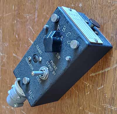
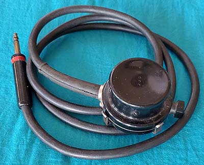
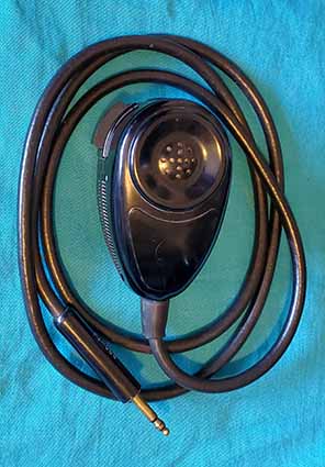
Chinese PLA Microphones (Vietnam War
Era)
- These microphones are the BEST performing of
the carbon mikes providing plenty of response, great sound with
impressive clarity and lots
of modulation when used with WWII-vintage transmitters. However, finding any of these Vietnam
War-era, surplus-People's Liberation Army (PLA) Chi-Comm
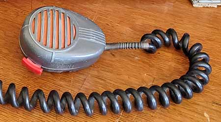
mikes these days (that are reasonably priced) will be difficult. These microphones, when stock
original, are in a
metal "Shure look-alike" handheld case that's usually painted
smooth semi-gloss olive drab. I've found one original Chi-Comm "Shure Knock-off" that was painted olive drab wrinkle finish
and another one that was original black wrinkle finish but nearly
all of those that are found will be a smooth OD finish paint (see photo
right for both types of
OD paint finishes.) Rather than the Shure-type slightly-rounded back with a mike-mount stud, the Chi-Comm
mikes have a flat back (this allowed the mike to lay flat on the
desk with the PTT "locked" for "hands-free" operation.) The PTT
switch actually is a rocker-switch that when in the down
position acts like a spring-loaded PTT but if the switch is pushed
to the up position, that's a "PTT locked" and allows releasing
button while maintaining the PTT action (just "rock" the switch to
the center position to unlock and go back to standby.) The
carbon element is hard-wired, so it isn't a "contact" type of
connection. The mike cable isn't a curly-coiled-type and the
"knock-off" PL-68 plug is just very slightly undersized so it will
easily fit into a
standard USA "68-type" three circuit mike jack,...but it isn't a perfect fit. Most
of these PL-68 "knock-offs" fit fine and work great in the
standard "68-type" three-circuit jack but sometimes they can be
difficult to remove from the USA-type jack (probably due to a
minor misalignment due the slight size difference.) If this is a
problem, then the "knock-off" plug can be changed to a standard USA
PL-68. >>> |
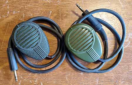
People's Liberation
Army (Chi-Comm) "Shure Knock-off" Mikes |
| >>> I own five of these Chi-Comm mikes. Two are Chi-Comm
carbon elements that
I installed into genuine vintage USA Shure 102C metal bodies and another two are all-original
functioning Chi-Comm mikes (shown in the photo above.) The
fifth is an EMS-94 Electret-Condenser microphone element
installed into an original black wrinkle finish Chi-Comm mike body (and it's profiled
further down this write-up in the "Electret" section.) All four of the true carbon
mikes have great response and,
although I hate to admit it, they sound
better than any other carbon mike I've ever tested. I've been using this type of PLA carbon mike over the past 15+ years.
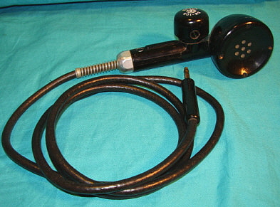
Pseudo-Shure 102C - Shure 102C body with Chi-Comm Carbon Mike Element Installed
- The primary carbon microphone that I use is a vintage Shure
102C metal-body with a carbon element salvaged from a Vietnam
War-era surplus, People's Liberation Army "Chi-Comm" Shure
look-alike microphone. This mike has tremendous response, good fidelity (for
a carbon mike) and provides lots of modulation capability. Since
the Chi-Comm element is "hard-wired" inside the mike body,
it's very easy to remove. >>> |
| >>> The fit into the Shure body is
perfect and the element can be mounted using the 102C
hardware. Since the Shure 102C was a handheld mobile-type
microphone, nearly all examples will have a "curly cord"
installed. Almost none will be fitted with a PL-68 plug so
that has to be changed. The Shure PTT button only functions
as a push-button. I did this retrofit about fifteen years
ago and I've had very good results using this mike with
several different ART-13 transmitters, with the
BC-375 transmitter,
with a GF-11 transmitter and with the
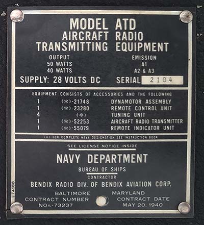
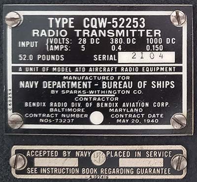
ATD transmitter. I use my other "102C conversion" with the
GRC-19 (T-195
xmtr + R392 rcvr. NOTE: The T-195 uses a very different Type
U-77
twist-lock, ten contact plug so having a second "102C
conversion" with the U-77 connector on the mike cable was necessary.)
Anywhere that a carbon microphone is the proper equipment,
these "102C conversions" work fabulously.
And, unless you tell someone, they look just like the
standard USA Shure 102C microphone. NOTE: I bought these PLA mikes on eBay
15+ years ago. They were cheap,...then,...about $15 each. I
haven't seen any listed on eBay in many years. A
recent 2025 search on the Internet turned up one source for these exact
type of microphones. "Enemy Militaria" has
some of these PLA microphones for sale. However, the price is
staggering,...$208 each! Ouch! |
Vintage Shure 102C
body with Chi-Comm
Carbon Element Installed |
|
Carbon -
A
LOSER - T-38C/RS-38-B WWII Original USN
Microphone for the ATD - The T-38C (aka RS-38-B) was a small
handheld mike that fit into the palm of the hand and had a PTT
button on top of the mike body (like a stop watch.) Most
were "noise-cancelling" mikes with three very small voice holes in
the cup although there are some types that were for ground use that
have a multitude of voice holes. I've tried a few of these types of carbon mikes, including NOS examples. I've always found that, if they work at all, the
response is usually very low due to carbon packing or, in the case
of used mikes, maybe fused carbon granules from excessive bias
voltage. To use one of the T-38C versions would involve testing
quite a few to find one that was responsive and then it would
certainly require extreme "close-talking" and an elevated voice
level,...yelling, in other words,...to actually modulate a
transmitter at a level that produced a decent AM Voice signal. I've
never heard an original T-38/RS-38 type of microphone actually being used "on the
air" on any of the mil-rad nets. I tried two different types of T-38/RS-38
mikes with a USN GF-11 transmitter and the response from either one
was way too low for anything other than testing.
The RS-38-B that I disassembled was a Telephonics version and it
was designed to replace the entire mouthpiece assembly for repair. The
two-piece element
can be taken apart and the diaphragm stays attached to the front
mouthpiece. The diaphragm's backside is gold plated,...most
carbon mike diaphragms are in direct contact with the carbon
granules and the gold plating maintains consistent conductivity. The rear part
of the element has the carbon granule cup and the
metal body with the insulated contact button. If you
disassemble the two-piece element upside down, all of the carbon granules will
spill out of the cup (that's not a problem if you plan on
scraping the element anyway.) Installing an electret replacement
element would require destroying the original carbon element to
refit the electret element. Then taking out the spring contacts in the
body would be necessary followed by hard-wiring the electret element to the body. I haven't done this so
I can't say how an electret element would sound in the very small
case that the T-38 and RS-38-B mikes use. There are several versions of this
type of carbon microphone design with slightly different physical
parameters, different designations and built
by companies other than Telephonics. |
Telephonics Corp. -
T-38C aka RS-38-B |
| Carbon -
A TYPICAL WWII-VINTAGE PERFORMER - T-17B WWII USA
"Ground-Base"
Microphone - The Shure T-17
is a very common and therefore an easy to find WWII vintage aircraft
microphone. But, not all T-17s were for use in aircraft. Some were for use
on the ground in buildings. The ground operations type are not noise-cancelling
and will have seven large voice holes in the mike cup. These mikes use
a bakelite body. I've had my "ground-T-17" example for about 20
years and it's an
all-original mike with original carbon element so the carbon granules are probably compacted
somewhat. Response is much better than a typical original T-17 but
much lower than the Chi-Comm mikes (as would be
expected.) Also, lots of noisy crackling sounds and that's a
common problem with
nearly all original WWII carbon elements,...well,...after
all, most of the original elements are 80+ years old.
Nearly all T-17 mikes were for aircraft operations and
are "noise-cancelling" types with three small voice holes in
the mike cup. "Close-talking" is almost always necessary
with any of these types of carbon mikes and speaking loudly also helps. Early
T-17 mikes have metal bodies that are easy to take apart and
work on. The cup is mounted with four, black-wax covered
screws. The carbon element is held in place against the
contacts when the cup is
mounted. The middle variety, A, B and C, are bakelite body
that have a small panel the can be removed for access to the
PTT switch. The cup is mounted with four screws that are
black wax-covered (if the mike hasn't been tampered with.) Very late T-17 mikes (the "D" versions) have
a integral mike cup and element that's a complete, sealed unit. The
entire front of the mike was supposed to be replaced if problems
developed. The handle of the body is molded in "one-piece" with no
easy access to the PTT switch wires unless the mike is fully
disassembled (if that's even possible.) Earlier T-17
mikes can be rebuilt but the "D" versions usually can't. It might be
possible to somewhat resurrect original T-17 carbon elements
by tapping the element against the table to "jar" the
carbon granules loose
but they usually don't ever return to full response (after
all,...remember the 80+ years.) |
Shure T-17B with "Ground-Base
Operations" Cup |
| Carbon -
A RARE GOOD ONE - NOS T-17
"Noise-Cancelling" USA Aircraft Microphone -
I do have another example of the Shure T-17 that's NOS in the
original box. It's a T-17 aircraft version with noise
cancelling cup and with a treated-cloth spit-cover. It's an early T-17 that has
the metal body
with a bakelite cup. Despite its pristine condition, the PTT button
was sticking and wouldn't return to the standby position after being
depressed. I had to remove the button and clean the molding burrs
and then very lightly coat the mating surfaces with light-weight
grease. PTT operation was then normal with no sticking. The DCR of
this carbon element measured about 2500 ohms (I used a
modern DMM for this DCR measurement since the voltage
applied would then be very low.) Most carbon mikes will measure
around 1200 ohms up to maybe 3500 ohms. It's not critical
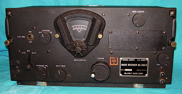
since the resistance changes with voice (sound) pressure. I connected the T-17 to the ATD. I monitored the output
using headphones on the Reception Set R106 (antenna disconnected)
and also using the Leader 505
oscilloscope as a waveform monitor. I was completely surprised! This NOS T-17
had plenty of response and sounded pretty good (but the
audio was very
"carbon-y.") It provides lots of
modulation (as seen on the oscilloscope.) It was a little
"rough" sounding in the 'phones but I was surprised that placing the
spit-cover on the mike head helped to smooth the rough sound a bit. I think if
this mike was used regularly, it probably would continue to improve.
As it is, it works better than any other "original" T-17 I've ever
used. NOTE: The
EMS-94 Electret-Condenser element will physically fit into the head of
the T-17 mike. I don't have a complete "junker" T-17 and I
don't want to disassemble either of my original T-17 examples.
The mouthpiece screws are covered
with a black wax material on original mikes and if a
T-17 has been taken apart, it's obvious. My two complete T-17s
are original with the black wax in place. The one "junker" T-17B body
that I have is incomplete and has been "gutted" so I don't know how the spring
contacts were installed or if the T-17 even used spring
contacts. If there's a
problem with the EMS-94 not interfacing the spring contacts,
the element can be "hard-wired" for the connections. Other
fitting problems might also be encountered depending on the
depth involved in the body, how the mouthpiece fits and the
thickness of the EMS-94 element. Until I find a "junker"
T-17 that's complete to disassemble and measure, I can only
say the the EMS-94 does fit as far as its diameter fitting
into the T-17B head. |
NOS Shure T-17 early
style with
metal body, aircraft-type "noise-cancelling" cup and spit-cover |
| Carbon
- MINE'S A "BEATER" - BUT
IT WORKS! - Roanwell
RM-15 and Roflan M-15/UR, T-17 "look-alikes" - There's
a T-17 "look-alike" microphone that was designated as
RM-15 that was built by Roanwell Corporation of New York
City, NY. An identical microphone was built by Roflan Company and
was designated M-15/UR. It's probable that somehow Roflan
and Roanwell were connected since the names are so similar,
the mike IDs are so similar and, physically, the microphones
appear to be identical. The microphones date from the 1950s so they appear
to be updated T-17 versions although the handle is built similar
to the early, metal-body T-17. They use the same SW-109 push-button but
with the Roanwell/Roflan logo instead of the Shure logo. The body of
the RM-15/M-15/UR is metal and by removing three screws it will
split-in-half for disassembly (like an early T-17) allowing
easy access to the PTT switch. The black bakelite cup has
seven small voice holes and lettering is embossed on the rim
of the cup states "TALK WITH LIPS TOUCHING MIC." There's a
segmented gap between the back of the cup and the mike body.
The carbon element assembly is made up of the front
mouthpiece behind which the carbon element is
mounted with four screws. Also, the carbon element is hard-wired
through two holes to connect to terminals that are also part
of the back of the element and mouthpiece assembly. The carbon element
can't be dismounted from the mouthpiece unless the carbon
element wires are unsoldered and the four screws removed. The body wires (from the
PTT switch) are also soldered to these terminals. From
disassembling my Roflan M-15/UR, I think the repair
process was to just replace the entire "mouthpiece/carbon
element" as one piece since this only required removing
front four
screws on the mouthpiece and unsoldering the two body wires, connecting up the
new replacement piece and remounting the mouthpiece assembly to complete the task.
This would have been quite easy to accomplish. The segmented
(and open behind the element - like venting)
area behind the mouthpiece assembly is a mystery. It doesn't
seem to have any functional purpose. There are two
capacitors inside the mike head, one for RF suppression on
the mike element and the other for transient suppression on
the PTT contacts. These mikes may have
been used in vehicles or other ground applications.
Interestingly, the M-15/UR shown in the photo was found with a Roanwell carbon element installed (and it fit perfectly
and looked original.) As stated in the title, this
M-15/UR example was a "beater" with missing screws, broken screws, PTT
contacts forced together and many other indicators of
indifferent (or incompetent) rework. I totally
disassembled the M-15/UR, replaced broken or missing screws,
rebuilt the PTT switch, cleaned the contacts, disassembled
the element,...rebuilt
the entire mike, in other words. And, to my complete surprise, after the
rebuild, the
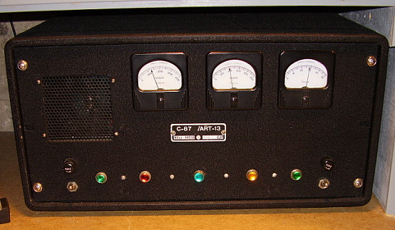
microphone worked. I tested it with the ART-13A monitored
with the FNIRSI 'scope and the Collins 51J-4 receiver with
Trimm 'phones. I was easily able to achieve "cut-off"
although it did require close-talking (and with the
lettering on the mouthpiece, "TALK WITH LIPS TOUCHING MIC."
I suppose that should be expected.) The M-15/UR sounded
like a typical old military carbon microphone,...but I was surprised that
it even worked at all. |
Roflan Co. M-15/UR -
T-17 "look-alike" |
| Carbon -
NORMALLY USABLE - Kellogg/U.S.
Army Signal
Corps T-32 - Gound-Base Use - This is a real
antique dating from the 1930s but T-32s were used by the
Army up into the 1950s because of its durability and decent
performance at ground stations. The carbon element is a
K1-type that was also used in 1930s Army Field Phone
handsets. The K1 is very large with a large diaphragm. The
front mouth piece has lots of small holes for a
better-than-usual pressure transfer. This seems to result in
a good response and
the reproduction is usually seems to have more bass than
expected from a military microphone. The K1 element in
this particular T-32 is dated 1938, so it's pre-WWII. The
interesting thing is that this K1 still has a nice
response and will modulate a WWII transmitter at a usable
level. The small lever on the side of the grip is the PTT
switch and it has "PRESS TO TALK" embossed on the lever. The
plug on the end of the cable is a standard PL-68 (I don't
know how I hid the cable for the photo,...maybe there wasn't
one installed when I took the photo.) The K1 element is held in place by two mounting
screws and then there are two contact clips that are also
screw mounted. The front cover is mounted with four small
2-56 machine screws. The K1 element is actually mounted to
the back of the front cover with the mounting screws and
contact clips on the back of the front cover. Two wires are
routed back to the head connections. Although, with the
amount of space available in the T-32 head, mounting a
modern electret microphone might be easy, the usual K1
element normally will have a very usable carbon mike response
and can properly be used on vintage ground-based
Army transmitters such as the BC-191. |
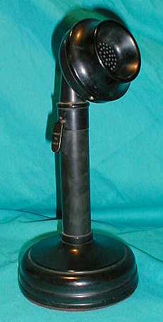
Signal Corps/Kellogg
T-32 - K1 element dated 1938 |
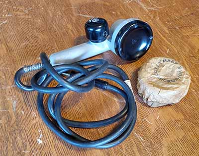
| Carbon
- Electro-Voice 210-S using a Modern (1987) Aircraft Carbon Microphone Element
- This 1987 aircraft carbon microphone element was in a plastic bag with a
company label stuck to the outside of the bag erroneously indicating
this carbon microphone element was built in 2004. It was NOS in the original packing (the bag) and was
"unused stock" from an aircraft rebuilding company in
Colorado. I've
seen similar elements advertised as being for Beechcraft
equipment but this bag didn't have any indication of what
the carbon element was for. A quick inspection of the
element revealed that the date-code on
the mike element was from 1987, not 2004 (repackaged, I
guess.) The element is much smaller than the typical
WWII carbon mike element so it could easily fit into either
a T-17 or T-38 microphone body. I decided to fit this element into an
Electro-Voice 210-S Carbon Microphone body that I've had for
quite a while. It's a large, beautiful handheld design
featuring a glossy
black bakelite body. The 210-S dates from the early 1950s. The carbon
element that was installed in the E-V was bad and
non-original. This new carbon
element was very close to the original E-V size so it
physically fit into the body fine. I soldered hook-up wires to
the new element and used black dense foam rubber as a shim
to allow using the original E-V element mounting. The "tricky"
part was getting the PTT switch to actually stay together
while the two pieces of the mike body (front and back)
were assembled. I had
to use fine 28ga. wire to hold the PTT switch contacts in
place while assembling the parts of the PTT switch
(including the compressed coil return spring) and once the
switch was together, I pulled out the wire so the two
contacts would "toggle" as the button was pressed. Of course, this
procedure took about three times trying to actually end-up successful.
Then, once the body was together, a test showed that the PTT
switch wasn't making contact, so the whole procedure,
including complete disassembly, had to
be repeated - and that had to be done twice (I wonder how
E-V did the assembly at the factory?) Finally, I got the mike body together with the
PTT switch working. The contacts were tested using a DMM to
confirm that they functioned correctly. Then a PL-68 plug was installed
on the cable. I tested the new carbon element inside the
E-V 210-S case using the ART-13A connected to the Collinear
Array with the signal monitored on the FNIRSI DPOS350P
'scope and the 51J-4 receiver. I had lots of response and
the waveform showed ample modulation with cut-off happening
every so often. The signal modulation sounded very good in
the 51J-4 receiver. I did notice that the element is
somewhat directional and I had to speak directly into the voice
holes of the mike body. That's probably the design and
results from how the mike element sets directly behind the
holes and perhaps the thickness of the bakelite case and
how that thickness relates to the depth of the voice holes
causing some directional characteristics. It's not a
problem, just something I noticed. The E-V mike works quite
well and is a really nice-looking microphone. It's now an
example of how a fairly modern carbon mike element can be
successfully installed into an older mike body and, of course,
this procedure can be applied to WWII-vintage microphones
that need a physically smaller type of new carbon element,
such as the T-17 and T-38. |
Electro-Voice 210-S, a "Beauty" from the 1950s |
|
Dynamic-Magnetic Microphones |
| Dynamic/Magnetic
- THE BEST - Astatic D-104
with TUG-8 Amplified G-Stand - Without a doubt, if
you don't like the "carbon mike sound," the D-104/TUG-8
combo is the BEST for providing a clean-sounding, high-level
audio output. It has no peers! - Well, this isn't a
"military" microphone,...it isn't even a dynamic
microphone,...but it will perform very well with
just about any military transmitter that provides the option
of using a dynamic or magnetic microphone. The Astatic
D-104 with TUG-8 stand is actually a crystal microphone element
driving a battery-operated transistor amplifier with adjustable gain. The output
impedance of the transistor amp will usually work well with military
dynamic inputs. Lots of audio highs with generally low
distortion and excellent articulation. Also, a high
modulation capability can easily be attained because of the adjustable gain feature. For a dynamic (crystal+amp) type
this is the BEST type and using it will avoid the typical "sound
characteristics" of a carbon mike. However, don't use a crystal mike directly
to a dynamic input since the crystal element impedance is very high
and won't provide very much response. You MUST use
the TUG-8 base with the transistor amplifier for proper
interfacing of a crystal mike with a WWII military transmitter. NEVER connect a
crystal mike directly to a carbon mike input,...the bias
voltage will destroy the crystal element. When using the Astatic
TUG-8 stand always select "DYNAMIC" or "MAGNETIC" as the
microphone type (the switch is part of the transmitter controls.) The TUG-8 amplifier has a fairly low output impedance
that
seems to be very compatible with most military transmitters that
were designed to use a dynamic microphone. It's also possible to use
a dynamic mike "head" such as the Astatic 10-D on the TUG-8 stand to allow easy
interfacing and impedance matching of a ham-type, hi-Z dynamic microphone to a WWII military transmitter.
The D-104/TUG-8 that I use has an original Astatic crystal
microphone element in the head. I bought two new D-104 elements
back in the early-1990s when they were still available from Astatic. Thinking that these elements would
always be
available, I installed one into a D-104 head and then sold
that mike (what a dummy!) Fortunately, I kept the other D-104 head with the
1990s Astatic element installed. That mike has done service
here for over 30 years now. It has excellent response in
an Astatic G-stand for direct-to-grid use with a Collins
32V-3 transmitter and I will swap stands to a TUG-8 if I
want to use this D-104 head with a military transmitter.
Crystal microphones are delicate and need to be treated
gently. Don't drop the mike on the floor. Don't expose the
mike to temperatures exceeding 125º F. The military NEVER
used crystal microphones because of their fragile nature.
More info that's specific to D-104 mikes,...read on,... |
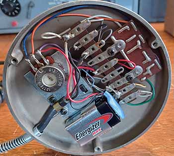
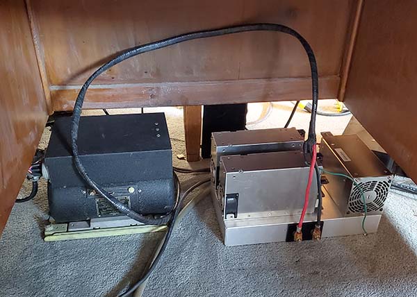
Astatic TUG-8
solid-state, battery-operated amplifier that is located in
the base of the stand. The PCB is the amp and the potentiometer controls the
audio gain. The 9-volt battery and the amplifier are
only "on" when the grip-bar is pressed. |
| IMPORTANT
NOTE: KOBE-TONE CRYSTAL ELEMENTS INSTALLED in D-104 HEADS
- Be
aware that many D-104 microphone heads no longer have their
original Astatic crystal element. When Astatic was sold in
2001, the new company stopped making D-104 mikes and
elements. After that, the only "newly-made" crystal
microphone elements available were from Kobe-tone (a
Japanese manufacturer.) These crystal elements were easy to
purchase from Mouser Electronics for about $5.00 each. Not
surprisingly, these were used as replacement elements for
quite a large number of D-104 mikes that had bad crystal elements. The problem
was that no two Kobe-tone elements sounded the same. Some
were okay but many were terrible sounding and none of them sounded
like the original Astatic crystal element. The original
Astatic D-104 crystal element was about 2.5" in diameter and
the thin aluminum diaphragm was the same size, covering the
entire front of the bakelite case used for the
Rochelle-salts crystal element. This diaphragm was covered
with a thin fibrous pad that was glued directly to the rim
of the diaphragm for
"breath noise" suppression. This almost direct exposure of a
large diaphragm to the screen on the mike head
(that had black grille cloth installed) provided excellent high-end audio
frequency and very high output voltage (piezo-electric
effect.) The Kobe-tone
element was available in two sizes, one at 1.9" diameter
and one that was about 1.25" diameter,...both quite a bit smaller
than the original Astatic element. Also, the Kobe-tone
element had a metal cover over the diaphragm with 13 sound
holes (in the larger element.) Since the Kobe-tone was so different in design than
the Astatic, it's not surprising that they didn't sound very
much alike. Most Kobe-tone
crystal elements, if used direct-to-grid, lacked any bass
response (even with a 5meg grid shunt) and also had a much lower
output than would be expected from a crystal element. BUT, if the Kobe-tone was
used in a D-104 head with the TUG-8 base, the
transistor amplifier usually compensated for most of the differences
in output level. On a TUG-8 stand, the Kobe-tone could
produce decent audio at a high output level. The Kobe-tone
crystal elements are no longer being produced, so all that's
available nowadays would be NOS stock Kobe-tone
elements from private individuals or an extremely rare,
original, NOS Astatic D-104 element (or even an old working
original D-104 Astatic element.) |
|
Kobe-tone
Crystal Microphone Element |
Original
Astatic D-104 Crystal Microphone Element |
|
| Dynamic/Magnetic -
A LOSER - Turner U9S Multi-Impedance Dynamic
- It's fairly difficult to find true dynamic
microphones with a low impedance option of between 150Z to
250Z. They're around but they usually are professional mikes
used in broadcasting or public address. Many types require
some wiring changes inside the mike body to select various
impedance options. Some early
dynamic mikes had switches that allowed easy changing of the
impedance. The Turner U9S was a
small early
dynamic
mike with an impedance switch that had color-coded indicators. Blue
was 25-50Z, Red was 200-250Z, Black was 500Z and White was
Hi-Z with the slot of the switch shaft pointing to the Z
selected. I had to make a cable for the U9S with the proper
three-pin connector to fit the mike head. A PL-68 was
installed on the other end of the cable. The U9S doesn't
have any type of PTT. The ATD manual has a paragraph
regarding microphones without PTT and indicates that the
THROTTLE SWITCH can be utilized for a PTT. This requires a
PL-55 plug and a short two conductor cable with a open and
close position switch. I already had a THROTTLE SWITCH cable
that I use all the time for "tuning up" so one didn't
have to be built. The mike is on all the time but that
shouldn't be a problem. I set the U9S to 200-250Z and connected the
mike to the ATD (the dynamic mike R-load is 300 ohms.) The Turner U9S sounded pretty bad. Very low
modulation. I switched the impedance to 500Z and that was a
very slight improvement but the mike output is just too low (the
ATD doesn't use an audio input transformer for Z-matching,
only resistors, but the ATD does provide a C-coupled dynamic mike preamplifier
stage.) The sound quality was okay. Compared to the
D-104/TUG-8, the Turner U9S really isn't usable. With some searching, finding
a 150Z to 250Z dynamic microphone isn't too difficult but
don't expect great performance.
NOTE: The ART-13A uses an audio input
transformer for both carbon and dynamic microphones. This
U9S was also tested with the ART-13. It performed best when
set at 200-250Z. I was able to hit cut-off if I close-talked
the mike,...loudly,...but the sound quality was not that good. |
|
 |
Turner U9S
Multi-Impedance Dynamic Microphone wasn't a good
choice. |
|
|
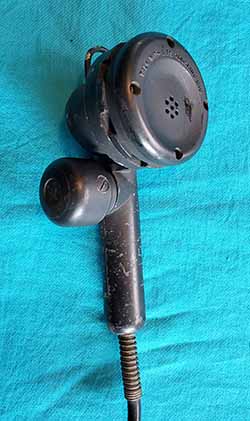
EMS-94 Electret-Condenser
Microphone "Replacement
Element" for Vintage Carbon Microphones
An Electret microphone is a Condenser microphone that
uses a metallic-coated flexible diaphragm that is in close
proximity to a backplate that has been coated with an "electret"
material. The electret material possesses an almost
permanent low-voltage static charge on it. As the metallic
diaphragm moves, the distance to the charged backplate changes the
value of C and, since there's a fixed-charge on the
backplate, a small varying voltage is generated across the
two plates involved. This voltage level is very low and
requires a transistor amplifier, usually a J-FET, to boost the output to a
usable level and to lower the output impedance to a value
compatible with most uses. In the case of electret
microphones that are used for
carbon microphone substitutes, the voltage to operate the
transistor amplifier can come from the carbon microphone's
bias voltage that is supplied by the transmitter. Since electret microphones don't use carbon
granules as a medium for sound transmission, the electret
output is free from "carbon hiss" and usually has low
distortion with a fairly wide audio bandwidth. |
| Electret -
I'M IMPRESSED - A Modern Mike Element
Installed in a Vintage Housing - Over the past ten
years or so, there have been a few types of electrec microphone modules offered
for sale
that were specifically designed for use in WWII vintage carbon mike
bodies. A popular version that was available a few years ago was built onto a small circuit board that
installed into the mike head. The electret amplifier was powered by
the carbon mike bias voltage. These electret PC board modules were designed
specifically for the T-17 "noise-cancelling" mike and did sound
slightly different when installed in other types of mike bodies. These
modules were available on eBay but are no longer being produced.
However, there's a new electrec mike element available
that's easy to install inside some types of old mike
bodies. G-Tel Enterprises, Houston, TX sells the EMS-94 electrec
microphone element for $7.75 each. These Electret elements are made specifically as replacements for the old Western Electric T1 carbon microphone found in telephone handsets. The
EMS-94 Electret amplifier is powered from the carbon bias
supply (the telephone landline provided a bias voltage for the
original carbon microphone in telephones.) Since this is a "telephone replacement" element,
it was designed to work in and sound like the old WE T1 telephone
microphone. It's also the same (large) size
physically at 1.795" diameter and 0.625" thickness. Since the EMS-94 is in a metal housing like the
original T1, the installation would
require a set of contacts that were like the type used in a telephone handset.
Those contacts would have to be fitted into a handheld mike body (although
it's easy to solder wires directly to the
element contacts for "ease of hookup" if spring-contacts aren't
already part of the microphone body.) For the mike
element to "sound correct" the mike body should
have a cover similar to a telephone handset. Mouthpieces
that are "noise-cancelling" tend to reduce the higher
frequency audio somewhat. |
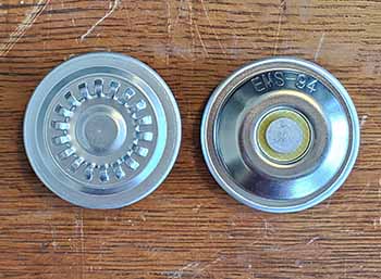
G-Tel EMS-94 Electret-Condenser
Microphone Replacement Element for Carbon Microphones
|
|
 |
Installation - The RS-38-B and T-38 WWII mikes
have too small of a mounting area to accept the EMS-94
without some modifications to the mike body. With contact
modification, the EMS-94 should fit into a T-17 without too
much trouble. The easiest way (for me) to use one
of these new Electret elements was to install it into one of the empty Chi-Comm
Shure knock-off cases I have. There's ample room inside the mike
body for the element plus room for a rubber spacer to allow
using the original spring retainer for the element. Also,
the front opening is quite large and unrestricted allowing
full-range audio response. The rubber spacer was 3/8" thick black
foam. It held the EMS-94
securely in the Chi-Comm case using the original Chi-Comm
wire retaining
clip. I cleaned the contact areas
on the mike element
and the soldered two wires for hookup. I used 400grit AlOx
paper to clean the metal surface and then the solder flowed
quite well allowing the wires to be easily attached. The
wire connections
eliminate the hassle of trying to come up with spring contacts.
In the mike body, the wires were connected to case ground and
to the PTT switch. The reassembled PLA mike with the EMS-94
element
was tested with the ATD transmitter. It seemed to have the
response of a good working-condition carbon mike and full
modulation was easy to achieve. The mike sounds something like a carbon mike
but that could just be the ATD audio components or my method
of testing. The response wasn't as intense as the PLA Chi-Comm
mikes but I was still able to easily fully modulate the ATD
(without
yelling.)
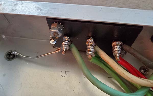
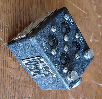
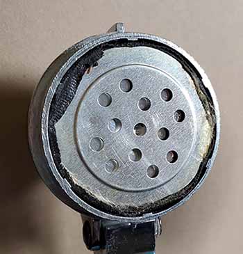
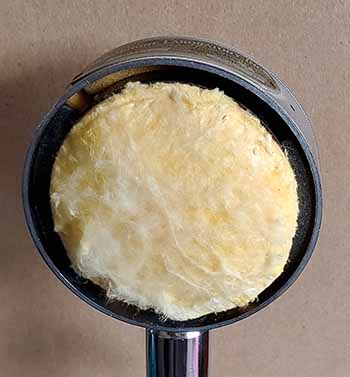
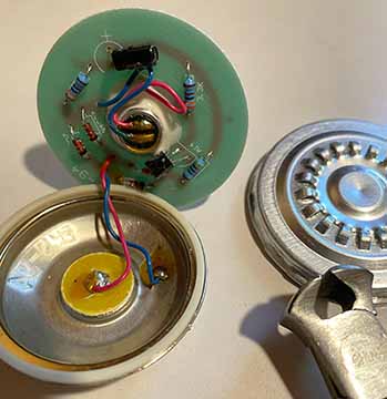
photo left: W7MS
decided that a look inside the EMS-94 would be informative. Mike used the tool
shown in the photo to unwrap the crimp of the front metal
piece of the EMS-94 to reveal "what's inside." As can be
seen, a circular PCB with nine components and the electret-condenser
mike glued to the PCB and wired into the circuit. Note that
the contacts have the connecting wires soldered directly to
the center contact button and to the inside of the metal
shell. Thanks to Mike, W7MS, for this interesting
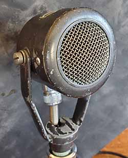
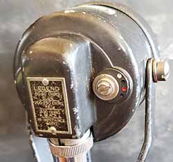
photograph.
|
|
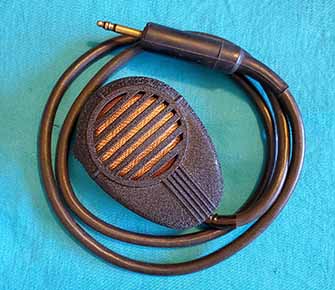
Electret in
an original Black Wrinkle Finish PLA body but the
grille cloth isn't original |
|
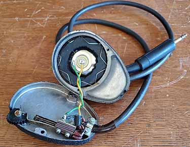
Inside the
Electret showing the spring clip hold-down and the
rubber spacer |
|
ART-13 Test
Turns Up Something Unexpected - I did an "on the air" test with ART-13A modulated with
this Electret mike. I noticed that the modulation was fairly
low on my monitoring oscilloscope but audio reports from the
other net participants were "sounded great" but
that's normally the way "on the air" microphone tests go
when operating in the "net" environment.
Luckily, Wavelength Radio recorded the NV-Mil-Rad Net (on
youtube) and I
was able to (later) listen for myself. I had made two
transmissions
using a D-104/TUG-8 mike and two transmissions made with the Electret mike. With the D-104/TUG-8 modulation was superb
and at a very high level resulting in a really nice audio presence. The Electret was at a very low
average modulation level of about 30% and this could be easily seen
on the recording's panadapter. There were times in the
recording play-back that I literally couldn't hear my audio but
the carrier was remaining strong. This was weird since the
Electret mike seemed to work fine with the ATD.
Why I Only Had 30%
Modulation Using the ART-13A - After the mil-rad net problems, I decided to retest the Electret. I again set-up the ATD
with the Electret mike. I was easily able to achieve full
modulation with the Electret as seen on the monitoring
oscilloscope. Obviously, the problem was with the ART-13.
This reminded me that the ART-13 carbon mike bias can have a
potential problem. If the particular ART-13 Audio Module never went through a military depot then it might still have the
original R203, a 15K
bias resistor, that results in a very low bias voltage that just about prevents using any type of carbon
mike. The value of R203 was changed in the later ART-13s to
a value of
4.7K (about 1943) and was usually changed if an
ART-13 went through one of the mil-depots. This lower
resistance increased the carbon mike bias voltage to allow
full modulation when using just about any good
condition carbon mike. This
ART-13A had been through SAAMA so I assumed the resistor
change had been made. But, I only used the D-104/TUG-8 on this
transmitter, in the DYNAMIC position, so the carbon mike bias
resistor
was never in the circuit until I tried the Electret. When
removing the Audio Module, I was surprised to find the
original 15K bias resistor was still present. I had
obviously worked on this Audio Module because some of the
capacitors had been replaced. I don't really know why I
didn't change R203 to 4.7K,...probably something in my mind
about maintaining originality (and not really needing the
carbon bias to be useable.) Since R203 wasn't used,...it
wasn't ever a
problem,...until now. So, I installed
a 4.7K 1W 10% CC as original (well, the original military MWO fix) and I was ready to test again.
Local Testing
-
This time the ART-13A no problem achieving 100% negative cut-off
using the Electret mike. Full modulation was very apparent on the
oscilloscope. I listened on the R106 receiver with no
antenna connected and using 'phones. The audio sounded like
a good dynamic mike, not as many highs as the D-104/TUG-8,
but still very good audio quality. I retested with the PLA
carbon mike and the response was somewhat more than the
Electret, but not by much.
The upshot of this ART-13 testing shows that the output of
the Electret mike is definitely dependent on the level of
the bias voltage from the transmitter. So, if the EMS-94 has
low response, check you transmitter's carbon bias level to
be sure it's providing a sufficient voltage level. Verify
the value and functionality of the bias circuit components
if there's a problem.
UPDATE: Oct 12, 2025 - I was NCO of the NV
Vintage Mil-Rad Net today and I used the ART-13A with the
Electret EMS-94 in the PLA body as the microphone. I
monitored the signal waveform locally on a FNIRSI DPOS350P
oscilloscope. The modulation showed cut-off was being
achieved fairly often and the level of modulation was quite
good. All went Q5 on the net but I was interested in
the Wavelength Radio recording of the mil-rad net on YouTube.
This time, on the recording, I was sounded much better with
lots of presence but I really
wanted to see the panadapter display. The panadapter showed
the signal
was about 10kc wide and that indicated that the audio response was
easily at the 4000hz upper audio frequency spec that the
ART-13 is rated for and the
upper-end audio frequency wasn't limited by the EMS-94 (or the PLA
body.) The
spectrum was full of audio indications out 5kc each side of
3.9745mc (net frequency is 3.974mc.) The vertical panadaptor showed a good level of modulation that again
looked about 10kc wide. The EMS-94 sounded excellent with a
good representation of my voice characteristics with lots of
presence. 100% better
than the last "on the air" test.
|
|
CONCLUSIONS: - The EMS-94 Electret-Condenser
mike element is an excellent replacement for a defective
carbon mike element. It sounds good and modulates very well if the carbon mike bias
voltage of the transmitter is at a sufficient level. It's
large size (1.795" diameter and 0.625" thickness) might limit what
WWII mike bodies it can be installed
into. Since the EMS-94 easily fit into the PLA mike body, I
would think it would be easy to fit into the USA Shure 102C body
or any similar size metal handheld mike body. Also, soldering
wires to the contact button and the shell doesn't do any
damage since the EMS-94 is actually a circular circuit board
inside the housing that has the electret-condenser mike and nine other small
components mounted on the PCB. Two wires are soldered to the
contact button and the shell inside the housing, so
soldering wires externally is okay and definitely makes
installation easier.
Ordering the EMS-94 from G-Tel is easy. The elements are
$7.75 each and because of the minimum order requirement,
you'll have to order at least two EMS-94 Electret elements.
There's also a very small shipping charge. You can pay with
a credit card or PayPal. You can order the EMS-94 Online from:
www.payphone.com/EMS-94-Electret-Condenser-Microphone.html
|
|